Untitled
Incipient Fault Detection in 33/11kV Power
Transformers by Using Combined Dissolved Gas
Analysis Technique and Acoustic Partial Discharge
Measurement and Validated Through Untanking
Mohd Raffi Samsudin
Ahmad Qisti Ramli
Ahmad Berhanuddin
Young Zaidey Yang
Researcher, High Voltage
Tenaga Nasional Bhd
Universiti Tenaga
Tenaga Nasional Bhd
TNB Research Sdn Bhd
Selangor, Malaysia
Kajang, Malaysia
Kajang, Malaysia
Abstract- Power transformer consists of components which
Electrical fault in power transformer can be categorized into
are under consistent thermal and electrical stresses. The
two which are Partial Discharge and Arcing.
major component which degrades under these stresses is
The Partial Discharge (PD) is the pre-breakdown of the
the paper insulation of the power transformer. The
paper insulation. A PD in a transformer occurs when the
electrical fault can develop into thermal fault such as
electric field in a localized area changed in such a way that
localized insulation burning or hot-spots. Any fault in the
localized current stream is produced. This localized current
transformer can be detected by using Dissolved Gas
will produce current pulses that are measurable at the output
Analysis technique. In this paper, the detection of
of the transformer. PD can be classified into three categories
electrical and thermal faults in 14 units of 33/11kV, 30
which are voids, coronas due to sharp edge or floating
MVA and 15MVA transformers were done by using
components and surface tracking. However, the detection of
Dissolved Gas Analysis (DGA). Then, the acoustic partial
the PD created by floating component and sharp edges did not
discharge test was carried out to detect the activity and
yield any useful information about the insulation because their
locate the source of the electrical fault. All the
appearance is not directly related to the condition of the
transformers were untanked and the inspection was done.
insulation. Besides, the PD due to the floating components and
From the inspection done, there were a few incipient faults
sharp edges will give rise to the Hydrogen and Methane
detected such as overheating due to loose connection,
content in the insulation oil. This will eventually give a false
sharp edges, insulation burning, choking effect due to
alarm on the insulation breakdown. Insulation breakdown
moisture and surface tracking in On-Load Tap Changer
happened mainly due to PD in voids and small cracks. Voids
(OLTC) compartment. As a conclusion, the combination
are defined as gaps in dielectric material which less dense than
of the acoustic partial discharge technique and DGA
the dielectric material itself such as gas bubbles in oil that fills
the transformer tank, or cracks in the paper insulation. The
technique have proved to be a useful tool in detecting and
void region has a lower dielectric constant than the
locating incipient faults in the power transformer.
surrounding material, which creates capacitance.
Keywords: Partial Discharge, Arcing, Dissolved Gas
A partial discharge can then occur when the electric field
Analysis, On Load Tap Changer (OLTC)
difference across the void if it exceeds minimum breakdown
field strength. A PD will eventually develop into arcing. Any
electrical fault in the transformer can be detected by using
Dissolved Gas Analysis technique. The DGA can be used to
Power transformer experiences consistent thermal and
differentiate between the types of faults in the transformer.
electrical stresses. The major component which degrades
However, DGA alone is not conclusive in determining the
under these stresses is the paper insulation of the power
electrical fault in the transformer. As a complement, acoustic
transformer. The insulation paper determines the life of the
partial discharge technique was used to detect the electrical
power transformer. The degradation of the paper insulation
fault in the transformer. In this paper, the detection of
will be accelerated with the presence of electrical fault.
electrical and thermal faults in 14 units of 33/11kV, 30 MVA
and 15MVA transformers were done by using Dissolved Gas
Modern Electric Power Systems 2010, Wroclaw, Poland MEPS'10 - paper 14.6
Analysis (DGA). Then, the acoustic partial discharge test was
carried out to detect the activity and locate the source of the
electrical fault. Finally, the transformers were untanked for
inspection and repairing.
II. ACOUSTIC DETECTION OF PARTIAL DISCHARGE [1]
The main advantage of the acoustic PD detection of partial
Figure 2: Acoustic PD Detection Circuit [1]
discharge is the location of the discharge occurrence. The
principle of the acoustic PD detection is the detection of the
The system frequency response (time constant) determines
pressure waves generated by the discharge within the
most system detection characteristics. The amplitude and
insulation which appears as a small explosion. The explosion
frequency characteristic of the signal that arrives at the sensor
will excite a mechanical wave, and propagates through the
and the ambient mechanical background noise determines the
insulation. The speed of the acoustic wave propagation
sensitivity and signal-to-noise ratio. Acoustic signals generally
depends on the surrounding medium [1]. The acoustic wave is
decrease at high frequencies due to absorption [1]. This effect
shown in Figure 1. The acoustic features such as duration, rise
is more for apparatus with large distances between PD sources
time, counts, energy and amplitude are used in partial
discharge detection. In acoustic PD detection, one need to
consider the reflection and refraction, geometrical spreading
On the other hand, the acoustic noise increases at lower
of the wave and absorption in the materials which will lead to
frequencies. The system is optimized through a tradeoff
changes of sound propagation.
between bandwidth, signal, and noise (Figure 3). Absorption
often limits the sensitivity and the thermal noise of amplifiers
increases as the square root of the bandwidth. This thermal
noise can influence the signal to noise ratio. Sometimes, one
discharge often results in multiple signals that propagate along
different paths to the sensor. The frequency response of the
system also determines which frequency components are
detected. As the speed of sound and propagation path vary
with wave type and frequency, the choice of sensor and
bandwidth determines the appearance of the signals.
Figure 1: Acoustic Wave [1]
The PD impulses has a short duration resulting compression
wave has frequencies in the ultrasonic region [2]. The
frequency range is between 10 Hz and 300 kHz. In air and
gases, microphones are usually used as sensors. On the other
Figure 3: Signal and Noise vs. Frequency, Indicating the Basis for
hand, piezoelectric transducers as acoustic emission (AE)
Determining the Acoustic Detection Bandwidth that Provides Optimum
Signal to Noise Ratio [1]
sensors offer the best sensitivity for detection of ultrasonic
waves in the enclosure [2].
B. Location of Discharges [3]
A. Design of Acoustic PD Instrumentation [1]
The possibility of PD activity location is one of the major
features of acoustic discharge detection. Location can be
Acoustic partial discharge detection apparatus consists of a
based on either measurement of the signal arrival time at a
sensor, filter, preamplifier, and some type of data acquisition
sensor (Figure 4(a) and 4(b)) or on measurement of signal
instrument as shown in Figure 2.
level. The intensity of the wave decreases as a function of
distance from the source when a wave propagates through a
becomes complicated. If the electrical signal cannot be
detected, a triangulation can be carried out as a simultaneous
measurement with several acoustic sensors. In a locus, the
source must be located on a hyperboloid between the two
sensors. This can be determined from analyses of time lag of
the signal. All locations on a hyperboloid have the same time
lag between the signal arrivals at the two sensors. If the signal
is repetitive, one of two sensors can be moved until the
acoustic pulses arrive simultaneously at the two sensors where
the location of the PD source is in between them. The simple
rule is the signal magnitude will be high if it is close to the
source. Then, only one sensor is required and is moved around
until the position for maximum signal is located. The
frequency of the signal will be higher as it reaches closer to
C. Triangular Method for Location [1]
Figure 4 (a): Triangulation of Source Location Based on Time of Flight
Measurements Based on Measurement of both Electric and Acoustic Methods
The triangulation method is time consuming and the result
of the PD detection may diverge from it location [1]. As an
alternative, the location calculation is derived from the time-
distance relationship implied by the velocity of the sound
wave. The absolute arrival time, t, of a hit in an event can
combine with the velocity, v, of the sound wave to calculate
the distance, d, from the sensor to the source [1] as in equation
d =
v ×
t (1)
The distance between two points depends on the dimension
of the object. The majority of the location modes are a
variation of 2 dimensional source locations in a plane. In
many cases the 2D plane will wrap around a 3 dimensional
object. For two points in 2D, the distance equation is just the
Pythagorean Theorem expressed in Cartesian coordinates as:
d = (
x −
x ) + (
y −
y ) (2)
This calculation is complicated because the exact time the
event origination is unknown. To overcome this problem, all
Figure 4 (b): Triangulation of Source Location Based on Time of Flight
the times are considered relative to the first hit in the event.
Measurements Based on Acoustic Methods [1]
Each arrival time difference for each sensor is referred
This results from several mechanisms including geometrical
relatively to the distance from the first hit sensor. For the
spreading of the acoustic wave, acoustic absorption
second hit sensor as relative to the first hit sensor, a difference
(conversion of acoustic energy to heat), and scattering of the
equation can be written as:
wavefront. These phenomena result in a reduction of the
t −
t = (
d −
d ) /
v (3)
intensity of the wave as it moves away from the source. In
practical situations, a location based on a time-of-flight
The distance equation (2) can be combined with the
measurement requires two or more simultaneous
difference equation (3) to get:
measurements in order to use triangulation to determine the
source location. Additional option which will ease the PD
t −
t =
[ (
x x)2 (
y y)2
x )2 (
y
detection is to measure the electrical signal simultaneously
with the acoustic signal. If the acoustic propagation velocity is
known, then calculation of the source location will become
s and
ys are the unknown coordinates of the source.
The equation contains two unknown and cannot be solved by
itself. To get a second equation with the same 2 unknowns, a
3rd hit is added to the event to get:
However, different wave components travel along different
paths in a structure which makes the location determination

t −t =
[ x( x)2 (y y)2
x )2 (y y )2 /
These simultaneous equations can then be solved for xs and
ys .The problem with this approach is that it gives more than
one source location per event and if there is any error in the
timing values, the source location can be wildly incorrect [1].
A better approach would be to average the data to produce a
single location. The equation given in (5) can be solved by
using multiple regressions. However, it does not actually
average the results of multiple 3 hit calculations directly. If
more hits are considered, the equation (4) and (5) and can be
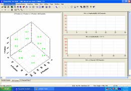
Figure 6: Software layout [6]
t is the time of arrival for the other sensors.
IV. RESULTS AND DISCUSSION
A field test was conducted on 14 units of transformer
The acoustic partial discharge test was done on 14 units of
suspected experiencing partial discharge activity. These
transformer for 24hrs. Oil samples were taken and sent to the
transformers have been selected based on its hydrogen and
lab. The DGA interpretation was done by using Roger Ratio,
methane level, which are more than 100 ppm and 50 ppm
IEC Ratio, IEEE ratio, Duval Triangle, Key Gas Analysis and
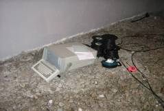
respectively [4]. The equipment and the software layout for
Doernenburg ratio. In addition, the transformers were
the acoustic PD testing are shown in Figure 5 and Figure 6
untanked to perform the inspection internally. Table I
summarizes the oil test results and the untanking findings.
TABLE I: DGA INTERPRETATION AND UNTANKING FINDINGS.
The location of the sensors should be similar with the layout.
Oil DGA Interpretation
After the sensors has been attach to the transformer tank,
Overheating and Partial
Loose Connection at On Load Tap
automatic sensor test (AST) was performed. This is to check
Changer (OLTC) termination
the operation of the sensors and the cabling connections to the
Partial Discharge
Sharp Edge at OLTC termination
sensors. The test was run for 24 hours so that it can capture
Partial Discharge and
OLTC moving contact tracking
the whole day loading cycle of the transformer. At the same
Partial Discharge and
OLTC moving contact tracking
time, oil sample was taken to capture the condition of the oil
during testing. After the testing completed, AST was
Burned Insulation
performed to check the condition of the sensors. A threshold
Partial Discharge
Wrong Cable lug sizing at OLTC
of 45dB was used for the acoustic testing.
Partial Discharge
Wrong Cable lug sizing at OLTC
Partial Discharge
High Moisture and Insulation
Partial Discharge
High Moisture and Insulation
Partial Discharge
Wrong Cable lug sizing at OLTC
Partial Discharge
Wrong Cable lug sizing at OLTC
Burned Insulation
Partial Discharge
Sharp Edge at OLTC termination
Partial Discharge
Sharp Edge at OLTC termination
Figure 5: The Acoustic PD equipment and sensors
T1 faced some problem with its OLTC termination. The
OLTC termination was loose thus created some discharge and
hotspot (Figure 7).
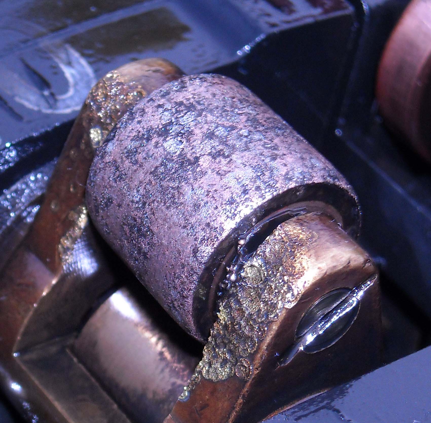
Loose connection causes Overheating
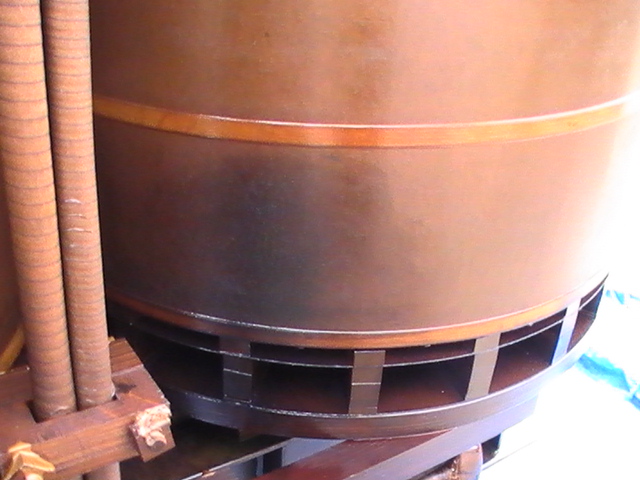
Figure 9: Some tracking observed at the moving contact (T3, T4)
Figure 7: Loose OLTC termination (T1)
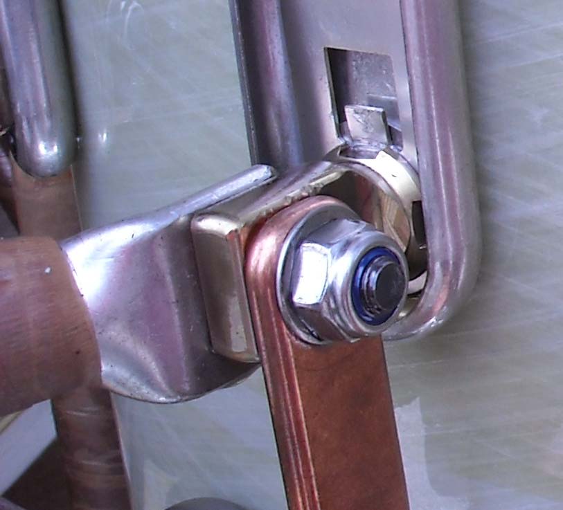
For the transformer T2, T13 and T14, partial discharge was
detected due to sharp edges at the OLTC termination (Figure
8). This type of partial discharge is called corona and will give
rise to the hydrogen and methane content in the insulating oil.
However, no secondary damage was detected due to this
For the transformer T3 and T4, some electrical discharge
signals were picked-up by the acoustic partial discharge
equipment from On-Load Tap Changer (OLTC) tank. The
OLTC compartments were opened and some tracking
observed at the moving contact. The tracking is due to the
contaminated OLTC oil which becomes conductive (Figure
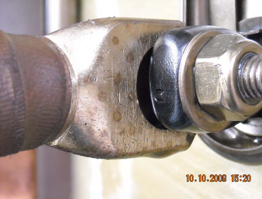
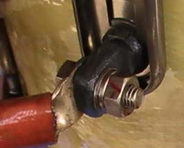
For the transformers T6, T7, T10 and T11, some discharges
were observed and distributed around the OLTC
compartment. The untanking findings revealed that the
Figure 10: Cable Lug with Gap (T6, T10, T11, T7)
discharges are due to wrong cable lug sizes used at the
termination. The wrongly sized cable lugs created air gap at
the termination (Figure 10).
Sharp edge caused Corona.
Note: The edge should be
bent instead of extruded out.
Figure 8: Sharp edges at the OLTC termination (T2, T13, and T14)
Figure 11 : Burned Insulation
[2] M. Muhr, R. Schwarz, "Partial Discharge Measurement as a Diagnostic
The remaining transformers (T5,T8,T9,T12) had
Tool for HV-Equipments", Institute of High Voltage Engineering and
experienced overheating due to PD and some insulation
System Management, Graz University of Technology, Inffeldgasse 18,
8010 Graz, Austria, IEEE 2006, Pg 195-198
burnings were detected. These transformers have been
[3] DISP with AEWIN User's Manual Rev. 3 November 2005, PAC Part# :
proposed to be repaired in the factory (Figure 11 and Figure
6320-1001, Sound Technology for Safety & the Environment,
Acoustics Corporation, Princeton Junction, NJ, Copyright@2005.
[4] IEC 60599,"Guide to the Interpretation of Dissolved and Free Gas
Analysis"1999-03.
[5] N.A. Muhamad, B.T. Phung, T.R Blackburn, K.X. Lai, "Comparative
Study and Analysis Of DGA Methods for Transformer Mineral Oil"
,Power Tech, 2007 IEEE Lausanne 1-5 July 2007
[6] I. J. Kemp, "Partial Discharge Plant-Monitoring Technology: Present
and Future Developments," IEE Proc.-Sci. Meas. Technology, Vol. 142,
[7] IEEE Std C57.104-1991,"IEEE Guide for the Interpretation of Gasses
Generated In Oil-Immersed Transformers"'1991.
[8] F.H.Kreuger,"Discharge Detection In High Voltage Equipment",
Temple Press Book, 1964.
[9] Mistras Holding Group,"Acoustic PD Measurement Manual",
[10] L.E Lundgaard, "Partial Discharge XIV, Acoustic Partial Discharge
Detection-Practical Application", IEEE Electrical Insulation Magazine,
Vol. 8, No. 5, September/October 1992, pp. 34-43.
[11] Yasmin H. Md Thayoob, M.R Samsudin, P S Ghosh and Ahmad B.
Abd. Ghani, "Analysis of Partial Discharge Signal Pattern in XLPE
Cable under Various Soil Conditions using Self-Organizing Map", IEEE
International Conference on Power and Energy (PECon), Dec. 2008,
[12] M.J. Mousavi and K.L. Butler-Purry, "A Characterization Methodology
for Distribution System Abnormalities Using Wavelet Packets and Self-
Figure 12: Burned Insulation
Organizing Map Neural Networks", Proc. of the 13th Int. Conf.
Intelligent Systems Application to Power Systems, 6-10 Nov. 2005, pp.
From the untanking and internal inspection, it has been
observed that most of the PD activities in the transformers are
[13] M.L Chai, Yasmin H. Md Thayoob, P S Ghosh Ahmad Zuri Sha'ameri
due to the manufacturing defect. The defects shown in Figure
and Mohd Aizam Talib, "Identification of Different Types of Partial
Discharge Sources from Acoustic Emission Signals in the Time-
7, Figure 8 and Figure 10 can be avoided during the
Frequency Representation", IEEE International Conference on Power
manufacturing process. These kinds of defects will give a
and Energy (PECon), Dec. 2006, Malaysia.
false alarm on the occurrence of PD in the transformer.
[14] C.M. Lee, A.Q. Ramli, P.S. Ghosh, Y.H.M. Thayoob and Z. Wang,
Furthermore, the PD activity due to the latter can degrade the
"The Effect of Different Partial Discharge Sources on Acoustic Waves
Propagation in an Experimental Tank", Proceedings of the XIVth
oil thus will reduce the insulation integrity of the transformer.
International Symposium on High Voltage Engineering, Tsinghua
University, Beijing< China, Aug. 25-29, 2005.
[15] Wen-Yeau Chang and Hong-Tzer Yang, "Partial Discharge Pattern
Recognition of Molded Type Transformers Using Self Organizing
Map", 8th International Conf. on Properties and Applications of
Based on the internal inspection done on 14 transformers, it
Dielectric Materials, June 2006, pp. 246-249.
has been found that most incipient faults can be prevented
[16] Shie Qian, "Introduction to Time-Frequency and Wavelet Transform",
during the manufacturing process. Typical defect observed
National Instrument Corporation, Prentice Hall PTR, 2002.
during the untanking were sharp edges, loose contacts and
[17] Berkant Tacer and Patrick J. Loughlin, "Instantaneous Frequency and
Time-Frequency Distributions", International Conference on Acoustic,
wrong cable lug sizing. These kinds of defects will give a
Speech and Signal Processing (ICASSP-95), Volume 2, Pages 1013-
false alarm on the occurrence of PD in the transformer. On the
1016, 9-12 May 1995.
other hand, the lack of OLTC maintenance caused internal
[18] Richard G.Lyons, "Understanding Digital Signal Processing", Addison-
tracking due to degraded insulating oil.
Wesley Publishing Company, 1997.
[19] FITST3-31, Facilities Instructions, Standards and Techniques in
Transformer Diagnostics. 2003, Bureau of Reclamation Hydroelectric
The acoustic partial discharge technique proves to be a
Research and Technical Services Group Denver 2003. p. 5-13.
useful tool in confirming the presence of partial discharges in
[20] Md. Amanullah, et al., Analyses of Electro-Chemical Characteristics of
the power transformer. This is supported with the detection of
Vegetable oils as an Alternative Source to Mineral Oil-based Dielectric
Fluid. 2005 IEEE International Conference on Dielectric Liquids, 2005.
incipient faults which have been validated through physical
ICDL 2005. , 2005: p. 397 - 400
inspection. The input from the acoustic partial discharge
[21] IEC61294, Insulating Liquids - Determination of The Partial Discharge
measurement served as additional information in diagnosing
Inception Voltage (PDIV) Test Procedure,, E. I.T. Committees, Editor.
the transformer incipient faults.
1993, International Electrotechnical Commission: Geneva, Switzerland.
[1] L. E. Lundgaard, "Partial Discharge - Part XIII: Acoustic Partial
Discharge Detection, 2005
Source: http://meps10.pwr.wroc.pl/submission/data/papers/14.6.pdf
Understanding Diabetes And Your Risk Presented by: Sheryl Bartholow, FNP-BC Family Medicine 10/13/2014 Important Notice The information contained in this document is for informational purposes only. It is not intended to diagnose or treat specific patients and should not be used as a substitute for the medical care and advice of your health care provider. In addition, this document may contain references to specific products and/or medications. Such references, whether by brand name or generically, are provided for informational purposes only and do constitute endorsement, recommendation, or approval by GRHS or its medical providers. Always consult a medical professional if you have concerns regarding your health. If you are experiencing a medical emergency, dial 911.
הרוםמה תרשרש "Chain of Tradition" The Newsletter of Traditional Congregation February-March 2015 Shevat-Adar 577 ‘ שת ןסינ ט Mark Your Calendars "Lunch and Schmooze with Rabbi Gordon" Tuesday, February 10 12 noon Wednesday, March 11 12 noon Join Rabbi Gordon for a relaxed lunch and schmooze—anything Jewish goes! See page 10 Knosh & Knowledge Brunch & Program

