Doi:10.1016/j.clinph.2007.11.177
Clinical Neurophysiology 119 (2008) 842–852
Non-provocative diagnostics of photosensitivity using visual
evoked potentials
Joost Vermeulen a,1, Stiliyan Kalitzin b,*, Jaime Parra c, Erwin Dekker c, Albert Vossepoel f,
Fernando Lopes da Silva d,e
a Quantitative Imaging Group, Department of Imaging Science and Technology, Faculty of Applied Sciences, Delft University of Technology,
Lorentzweg 1, 2628 CJ Delft, The Netherlands
b Medical Physics Department, Epilepsy Institutes of The Netherlands Foundation (SEIN), Lorentz de Haas Laboratory,
Achterweg 5, 2103 SW Heemstede, The Netherlands
c Department of Clinical Neurophysiology, Epilepsy Institutes of The Netherlands Foundation (SEIN), Lorentz de Haas Laboratory,
Achterweg 5, 2103 SW Heemstede, The Netherlands
d Center of Neuroscience, Swammerdam Institute for Life Sciences, University of Amsterdam, The Netherlands
e Instituto Superior Te´cnico, Lisbon Technical University, Portugal
f Biomedical Imaging Group Rotterdam, Erasmus MC – University Medical Center Rotterdam, The Netherlands
Accepted 8 November 2007
Available online 7 February 2008
Objective: Photosensitive epilepsy (PSE) is the most common form of reflex epilepsy. Usually, to find out whether a patient is sensitive,he/she is stimulated visually with, e.g. a stroboscopic light stimulus at variable frequency and intensity until a photo paroxysmal response(PPR) occurs. The research described in this work aims to find whether photosensitivity can be detected without provoking a PPR.
Methods: Twenty-two subjects, 15 with known photosensitivity, were stimulated with visual stimuli that did not provoke a PPR. Usingan ‘‘evoked response representation'', 18 features were analytically derived from EEG signals. Single- and multi-feature classificationparadigms were applied to extract those features that separate best subjects with PSE from controls.
Results: Two variables in the ‘‘evoked response representation'', a frequency term and a goodness of fit term to a particular template,appeared to be best suited to make a prediction about the photosensitivity of a subject.
Conclusions: Evoked responses appear to carry information about potential PSE.
Significance: This result can be useful for screening patients for photosensitivity and it may also help to assess in a quantitative way theeffectiveness of medical therapy.
2007 International Federation of Clinical Neurophysiology. Published by Elsevier Ireland Ltd. All rights reserved.
Keywords: Epilepsy; Photosensitivity; Visual evoked potentials; EEG
Diagnosing photosensitivity ) usually
involves provoking photo paroxysmal responses (PPRs)
Photosensitive epilepsy (PSE) is the most common form
with intermittent photic stimulation (IPS). If stimulation is
of stimulus induced epilepsy (
stopped as soon as PPRs appear, there is a small risk of
). It is found in 5% of the adult epileptic
inducing an actual seizure. Some patients, however, might
patients and in 10% of all children with epilepsy
refuse to have photic stimulation due to this small risk. In
). It is estimated that it occurs in approx-
any case it would be desirable to develop an analytical
imately 1 in 4000 of the population.
method that could predict whether the responses to IPS inthe sensitive patients would differ from those of normal subjects.
In this context one possibility would be to determine
Corresponding author. Tel.: +31 235588248.
1 Tel.: +31 15 27 81416; fax: +31 15 27 86740.
whether some properties of the visual evoked potentials
1388-2457/$34.00 2007 International Federation of Clinical Neurophysiology. Published by Elsevier Ireland Ltd. All rights reserved.
doi:10.1016/j.clinph.2007.11.177
J. Vermeulen et al. / Clinical Neurophysiology 119 (2008) 842–852
would yield useful information in this respect. Research on
). A sub-threshold paradigm, i.e. without eliciting
visual evoked potentials (VEPs) in these cases, however, is
PPRs, was used. The stimuli were black and white, and
rather sparse. Gokcay et al. showed that there were differ-
red and green sinusoidal gratings. The essence of their find-
ences in the visual evoked potentials of patients with two
ings is that spatial contrast can play a dominant role in
forms of epilepsy: childhood epilepsy with occipital parox-
revealing the potential sensitivity of these patients to visual
ysms (CEOP) and symptomatic occipital epilepsy (SOE)
inputs. No attempt for prognostic classification, however,
(The VEPs of both groups were also
was reported in their paper.
found to be different from control subjects. This research
Our approach focuses on quantifying features of the
was done with IPS at 1 Hz, which in general does not pro-
VEPs to IPS. A set of these features is then used to test
voke a photo paroxysmal response (PPR).
whether photosensitive epileptic patients and non-sensitive
In recent years, an increase of incidence of photosensi-
control subjects can be discriminated. Our strategy is to use
tive epilepsy, caused predominantly by increased exposure
non-provocative stimulation that is the closest possible to
to video games and television, has prompted researchers to
the most common provocative protocol used clinically.
deepen the study of the pathophysiology of human photo-
Accordingly, we use here responses to simple flashes (and
not checker boards) delivered at the generally non-provoc-
In our group (), we
ative rate of 2 Hz.
found that photosensitive and control subjects could be dis-
Instead of making an ad hoc selection of features that may
criminated using the phase clustering index (PCI) of the
be expected to yield a good classification, we started with a
EEG, or MEG, recorded during intermittent light stimula-
set of eighteen features, and afterwards we selected, those
tion at various frequencies, before a PPR was elicited. Using
that provide the best classification using statistical tests.
this stimulation paradigm, however, a PPR was ultimatelytriggered. The question we address in this work is whether
it is possible to make a prediction about whether or not thepatient is photosensitive using non-provocative stimulation.
Porciatti demonstrated a defect in the contrast gain con-
trol in a selected group of patients with idiopathic occipital
Twenty-two subjects were studied. Information of the
epilepsy compared to normal controls (
patients can be found in .There were three normal
Table 1This table gives information about the patients
Posttraumatic focal epilepsy
Abbreviations for clinical responses: MS, myoclonic seizure; GTSC, generalized tonic–clonic seizures; EM, eyelid myoclonia; CPS, complex partial seizures;FC, febrile convulsions; AS, absence seizures; S, subclinica; U, uncomfortable sensation. Abbreviations for AED (Anti Epileptic Drug): LTG, lamotrigine;VPA, valproic acid; GBP, gabapentine; LEV, levetiracetam; OCB, oxcarbazepine; CBZ, carbamazepine; ESM, ethosuximide; CLB, clobazam; LZP,lorazepam. Abbreviations for syndromes: JME, juvenile myoclonic epilepsy; JAE, juvenile absence epilepsy; IGE, idiopathic generalized epilepsy; SGE,symptomatic generalized epilepsy; GEFS+, generalized epilepsy with febrile seizures plus; PSE, photosensitive epilepsy; TLE, temporal lobe epilepsy. The‘*' indicates that patients were photosensitive in the past, but not anymore at the time of the recording.
J. Vermeulen et al. / Clinical Neurophysiology 119 (2008) 842–852
subjects, with no familiar antecedents of epilepsy. Two
ear fit of each trial is subtracted (‘‘detrending''). Our basic
patients had focal epilepsy (one posttraumatic and one
stimulus response model is:
with lesional temporal lobe epilepsy), without evidence of
RðtÞ ¼ N ðtÞ þ 1
photosensitivity, neither during several EEG recordings,
nor on clinical grounds. In addition, two patients with idi-
here R, N and S represent, respectively, the measurement,
opathic generalized epilepsy (one with juvenile absence epi-
the noise and the ‘‘true'' response signal. In the above rep-
lepsy and the other with juvenile myoclonic epilepsy) did
resentation, S(t) is the time-evolution factor while the coef-
show some degree of photosensitivity in previous record-
ficient ac quantifies the distribution of the response over the
ings, but this condition was controlled with medication,
EEG derivations and the coefficient ss represents possible
such that no evidence of photosensitivity was found during
trial-to-trial jitter in the responses. The latter can be due
the day of the recording. These patients were considered
to imprecise trigger localization or due to jitter caused by
for the purpose of this study as non-sensitive and are indi-
fluctuations of the EEG on-going activity. We assume fur-
cated with an ‘*' in .
ther that the noise N has all the 3 dimensions: channels,
The other 15 patients showed photo paroxysmal dis-
stimuli and time. We have also assumed here that the jitter
charges during appropriate intermittent photic stimulation.
can depend on the stimulus but not on the channels which
Two patients had symptomatic generalized epilepsy, the
limits our interpretation to non-propagating patterns.
others belonged to the group of idiopathic generalized epi-
Notice that for all stimulation trials the same acS(t) rep-
lepsies, mostly juvenile myoclonic epilepsy.
resents the stationary physiological response. To accountfor this, the symbol 1s " [1, 1, . . , 1] is introduced.
In short, Eq. assumes that the evoked response of a
2.2. Data acquisition
patient is stationary and that the system resets itself aftereach response.
Most data were acquired at SEIN using a LaMont 32
The objective of the following pre-processing phase was
channel amplifier and Harmonie 6.0 software (Stellate Sys-
to determine or estimate the individual factors in In the
tems, Montreal). The international 10/20 system was used
pre-processing phase several techniques were used as
for the electrode positions and the EEG data were sampled
described in Sections Different strategies
at 800 Hz. Some data were obtained from the VUMC (Free
were followed in order to find an optimal representation of
University Medical Center in Amsterdam) magneto
the response signal for our classification objective.
encephalography (MEG) center. The VUMC data wereacquired at different sampling rates, varying from 250 Hzto 625 Hz. To overcome this inequality, all data were
2.3.1. Alignment procedure
downsampled to 250 Hz.
Our first optional strategy was to find an adequate esti-
VEP investigation was carried on by means of a com-
mation for the ‘‘misalignments'' ss in To account for
mercially available stroboscopic photic stimulator (Grass
possible misalignment a computational scheme was devel-
PS33). The patients were seated on a chair in front of the
oped ) based on estimating the corre-
stroboscopic stimulator that was placed at 30 cm from
lation functions between the evoked responses. Here an
their eyes. The recordings obtained in the MEG center
alternative alignment procedure was applied that is also
were performed with a stimulator specifically designed to
correlation-based but less computationally expensive. The
project images in the shielded MEG environment
procedure can be found in .
In the MEG center, EEG data were measured
The ss found here can be inserted in formula to compen-
in addition to MEG data. Only the EEG data were used for
sate if required for the initial misalignment.
this analysis.
In order to record visual evoked potentials (VEPs) the
2.3.2. Taking the mean over trials
patients were stimulated with a flashing light at 2 Hz and
To further reduce the complexity of our data and
an analog trigger signal was recorded synchronously with
according to the assumption that the terms acS(t) are the
the EEG traces; only the first 333 ms of the evoked
actual evoked responses per channel, we average over
responses was used.
all trials to obtain
P cðtÞ hRðtÞ i ¼ hN ðtÞ i þ h1
sSðt þ ssÞis c
2.3. Signal representation
¼ acSðtÞ þ g ðtÞ
The interesting parts of the EEG recordings for this
Here, the notation Æ æa is used to indicate averaging. In the
study are the sequences immediately after the stimulus.
last formula the left-hand side defines the channel-depen-
Using the trigger timing information the data are cut and
dent triggered response, the average gc(t) " ÆN(t)csæs is the
arranged into a 3D response ‘‘cube'': channels (c) · stimu-
lus number (s) · time after stimulus (t), R(t)cs. For each
h1sSðt þ ssÞi SðtÞ has been applied. In the case when
channel one can select the response to any individual stim-
no jitter is assumed (ss " 0) we have simply SðtÞ ¼ SðtÞ. In
ulus; this is called a trial. After this procedure, the best lin-
the sequel we use the notation S(t) both for the aligned
J. Vermeulen et al. / Clinical Neurophysiology 119 (2008) 842–852
and the non-aligned estimations of the response's shape
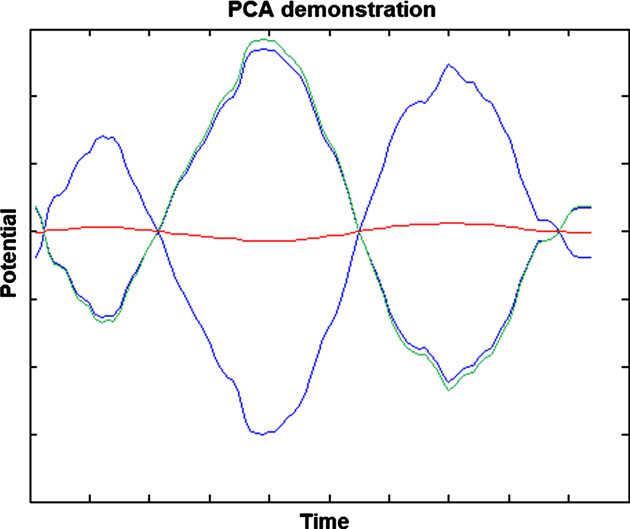
tion obtained with PCA (green line). From the red line it
appears as if nothing was measured. The green line shows
In addition to the averaged response , the response
that with the PCA weights, the shape of the signal is
statistical properties can be quantified by the phase cluster-
ing index (PCI) ().
Explicitly,
2.3.4. Representation approaches for response classification
In this work four different approaches for the quantifica-
tion of the evoked potential (EP) data are pursued. They
consist of combinations of what has been described in Sec-
tions . The text in bold is used to designatea specific representation for future reference.
F ðxÞ ¼ FT fRðtÞ g
1. Basic representation. Only the procedure of Section
is the Fourier transform of the signal. We consider here the
is performed. For each occipital channel (O1 and
overall PCI as in formula 3 with the following channel-
O2) the mean is taken over all responses. This yields 2
evoked responses per patient, one for each occipital chan-
nel. The subsequent features (Section ) are calculated
separately and averaged at the end.
2. PCA representation. Like the first method, but now
the resulting signals of the different channels are pro-
2.3.3. Principal component analysis between the channel
cessed according to Section . This representation
yields one evoked response (the principal component)
Since the EEG is measured at several positions on the
per patient.
head, one expects the amplitude to differ between channels
3. Aligned basic representation. The same as the basic
resulting in factors ac different for each channel. To sepa-
representation but after applying the alignment procedure
rate the common response shape S(t) from the weight fac-
described in Section .
tors ac in formula we can use the singular value
4. Aligned PCA representation. The fourth and most
decomposition technique that minimizes the total qua-
computational expensive method involves all three pre-pro-
dratic variation of the channel-specific noise gc(t). This
technique uses the covariance matrix
C ¼ covtðP cðtÞÞ
Selecting the eigenvector Vc corresponding to its largesteigenvalue we define the principal component (PC)
The remaining components, orthogonal to may then beinterpreted as ‘‘noise''. From formula it can be seen thatthe factor ac can be calculated as follows:
Finally, to give an estimate of the three-dimensional noise,we write in the form
N ðtÞ ¼ RðtÞ 1
t0 P cðt0Þ Sðt0Þ
t0 Sðt0Þ Sðt0Þ
In the above formula all quantities are known from the
Fig. 1. Demonstration of the effect of the PCA procedure. There are two
steps described in Sections . We assume
artificial ‘‘signals'' (blue lines), their mean (red line) and the representation
obtained with PCA (green line). In this particular case, it can be seen that
SðtÞ SðtÞ 1. Given the Pythagorean theorem, this
two signals with the same shape, but with only a different scaling, are
means that all spatial amplitude variation can be found
considered to be almost the same. The red line shows the mean of the two
in the channel weights a.
signals. According to the red line, nothing or very little was measured.
Maintaining the shape is beneficial when for example one measures the
In the effect of what has been described in Section
same signal at opposite sides of a dipole. (For interpretation of the
is demonstrated. The image shows two artificial ‘‘sig-
references to colour in this figure legend, the reader is referred to the web
nals'' (blue lines), their mean (red line) and the representa-
version of this article.)
J. Vermeulen et al. / Clinical Neurophysiology 119 (2008) 842–852
2.4. Quantification of the EP
After obtaining a representation of the EP, we proceed
with quantifying the features of the signal. In the previouschapter we have reduced the response signal complexity,according to the chosen representation from Sectionto several lower dimensional objects. For representa-tions 2 and 4 for example, we are left with the responsefunction , weights , jitter delays ss and the quantitiesPCI(x) defined in . In representations 1 and 3 theresponses are kept separate for the individual channelsbut the processing is the same. For these two representa-tions, the features per channel are averaged.
To compare different responses, additional data reduc-
tion is useful. In an explanationof features that are used is given. To simplify the notations,the proposed features are denoted by: (f.n) = {feature n,‘‘n'' stands for the number of the feature}.
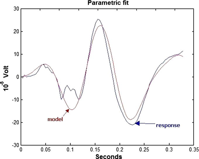
Fig. 2. Illustration of a response and the corresponding response function.
Features were derived from the representation described
The blue line shows the measured response. The red line shows the result
in Section an envelope function and from a response
of the parametrical fit. In this case a 2nd order fit was applied. (For
interpretation of the references to colour in this figure legend, the reader isreferred to the web version of this article.)
To obtain the envelope function, we first compute the
analytic signal.
dure to obtain the parameters of the second order fit.
H ¼ SðtÞ þ iHilbertðSðtÞÞ
shows a complete list of the features that are used in the
The absolute of the analytic signal is the envelope function.
Because of the uncertainties intrinsic to the source local-
AðtÞ jH ðtÞj
ization inverse problem, as well as questions concerning
This function has no zero crossings and is therefore well
parameters such as unequal contact impedances, we have
suited for computing features such as moments.
not attempted to extract any information related to the
The response model is computed by trying to minimize
spatial distribution of the response. Therefore we have
the distance between the actual response from Section
ignored the information contained in the coefficients ac
and a model function by means of which it is
from formula .
attempted to accurately describe the response.
The response model, k, is:
2.5. Classification
kðtÞ ¼ ekt sinð2 p m tÞ
2.5.1. Introduction
where m represents the frequency and k is a measure for
In this section we explain how the above quantities are
damping. Note that the frequency m has units Hertz be-
used to classify signals of different conditions. In this work
cause of the 2p factor in k(t).
the statistical power of the VEP features to discriminate
We assume that shape is more important than the over-
photosensitive from non-sensitive subjects is analyzed.
all scale factor, hence we quantify the goodness of fit by thedistance function D:
2.5.2. Kolmogorov–Smirnov test
ðSðtÞ SF kðtÞÞ2
The Kolmogorov–Smirnov test ) is used
to compare the distributions of feature values of sensitiveand non-sensitive subjects. This particular test has the
advantage that a priori no assumptions need to be made
about the distributions.
and the dot denotes a scalar product. A direct parametersearch method is used to minimize D, i.e. a range of values
2.5.3. One-dimensional classification
for k and m are tested. m values were tested between 0.25 and
To further investigate the features, the discriminatory
100 Hz in steps of 0.25 Hz; k values were tested between
information of features is tested directly. This was done
0.1 and 0.1 in steps of 0.001. illustrates an example
using simple one-dimensional threshold classifiers where
of an actual response and its model.
the values above a certain threshold are considered to
Note that this can be iterated several levels deep. One
belong to one class and those below the threshold to the
can subtract k(t) from the response and repeat the proce-
other. The classifier selects an optimal threshold for each
J. Vermeulen et al. / Clinical Neurophysiology 119 (2008) 842–852
Table 2A list of the 18 features that are used in the analysis
Average time of the response
Variance of the signal
Misalignment of the response
PCI of the driving frequency
Maximal phase clustering index
Frequency corresponding to f.8
PCI weighted mean frequency
Relative phase clustering index
First order damping factor of the response model
Second order damping factor of the response model
First order frequency of the response model
Second order frequency of the response model
Distance between the first order response model and the evoked response
Distance between the second order response model and the evoked response
feature separately so that the number of misclassified sub-
In this case also a threshold is set for Ca to minimize the
jects is minimal.
Although the voting scheme and linear classifier formu-
2.5.4. Feature combinations: voting scheme
las look the same, they are different with respect to how the
Using combinations of features may yield better classifi-
features are interpreted. The voting scheme translates the
cation results. One simple method to combine the discrim-
values of the features to a yes–no (0 1) vote per feature.
ination power of more than one quantity is to perform
In case of the linear classifier the values of the features
independently a classification according to each ‘‘member''
are used to build a feature space in which it is attempted
and then to postulate certain voting rules for a final
to separate the photosensitive from the control subjects.
If Via is the vote of feature i on patient a and Wi is a
2.6. Statistical significance of the classification
weight of feature i, then for Ca, the probable classificationof patient a we have:
2.6.1. Determining a significance threshold
For any classification approach, the significance level is
determined by the probability that the same results can be
achieved by a ‘‘random guess'' procedure. We require in
ia contains the votes (0 or 1) of each feature on each
patient based on the optimal threshold classification de-
this work statistical significance that limits the latter prob-
scribed in Section and A is a constant representing
ability to at most 5%.
possible bias in the classification.
To make sure that the chance is <5%, that the results are
The weight coefficients W
as good as random, 10,000 classification attempts on ran-
i and the bias term A are deter-
mined to minimize the overall classification error, as
dom data were done with a classifier. Since 10,000 classifi-
explained in .
cation attempts are done, one can assume that any result
the error of which ranks among the best 500 results, gives
and A determined, Ca can be calculated.
Finally, we find the common threshold for the class identi-
<5% chance to be random. Therefore the system is allowed
to make as many errors as the 500th best attempt. This
a that minimizes the classification error.
gives a distinct maximum allowed error. This maximum
2.5.5. Feature combinations: linear classifier
allowed error is called error(max).
The results with a linear classifier are also used in this
work. If, as in the previous paragraph, Wi is some weight
2.6.2. Procedure to find good feature combinations
of feature i and Qia is the actual value of feature i on
To find the good feature sets, all possible 2D, 3D, 4D
patient a, then we postulate
and 5D combinations of the 18 ) features are
tested. This is done with both the voting scheme and the
linear classifiers. From these feature sets a selection is made
based on the significance from Section .
To determine the optimal weights Wi and bias A, we refer
First, the size of the feature space is determined by look-
ing at the error(max) from Section and the error of
With Wi and A determined, Ca can be calculated.
the best feature sets for each feature space size. The error
J. Vermeulen et al. / Clinical Neurophysiology 119 (2008) 842–852
of this best set needs to be as low as possible. In addition,
the results need to be significant.
The training and testing here and in Section are
done on the same sets. This is no problem as this test serves
2.9. Robustness check
only to determine the size of the feature space and toremove feature sets that do not perform in accordance with
To get an impression about the consistency of our
the minimum level that is set by error(max).
results, multiple measurements of subjects are used. Of
Once the proper dimensionality of the feature set is
two subjects, one of which is photosensitive, there were
determined, all combinations that have an error <error
two data sets. These subjects will be referred to as subjects
(max) are used for further investigation.
A and B. From each of these two subjects, the measured
The results of this procedure are feature sets of proper
evoked responses are inspected visually. Additionally, it
dimensionality that can separate the two classes with a cer-
is verified that both measurements appear near each other
tain degree of significance.
in the feature space.
2.7. Cross-validation tests
To find which feature sets yield the best classification
3.1. Kolmogorov–Smirnov test
results, two tests are applied. First a leave-one-out cross-validation test is done. Leave-one-out cross-validation
In the probability is given,
involves using a single observation from the data set as
for each feature (f.n), that the distributions of sensitive and
the test data, and the remaining observations as the train-
non-sensitive subjects are the same. This is done for the
ing data. This is repeated until each observation in the sam-
four different representations.
ple is used once as test data. The errors of all repetitions are
shows that the align-
Additionally, a hold-out validation test is done. In the
ment procedure is not very beneficial. This suggests that
hold-out test a set of measurements is randomly split in a
the alignment destroys discriminatory information and/or
training (70%) and a testing (30%) part following prior
probabilities. The hold-out cross-validation procedure is
repeated 50 times and the results are averaged.
The best results can be seen in .
Only those feature combinations that have significant
In this case the basic representation is used.
classification performance and of proper dimensionality
The figures show clearly that the distributions of feature
(see Sections are used in this test.
f.15 (m) for the two groups of subjects are very different.
This is also the case for features f.8, f.11, f.17 and f.18.
2.8. Inspection of relevant features
From this point onwards we consider only the EP repre-
sentations where alignment is not involved.
The best sets from the cross-validation tests are
inspected taking into account the occurrence of specific fea-
3.2. One-dimensional classification
tures and feature combinations. The feature sets that had across-validation error <25% are further considered. The
In 1D classification the simple threshold from Section
percentage (25%) is chosen arbitrarily.
is used. The error for f.15 is 13.6% (=3/22, cf.
Additionally the best features are studied using ROC
This is when the basic representation is
(Receiver Operating Characteristic) curves. ROC curves
used. The result of the method that involves PCA appears a
are used to quantify the performance of a classifier in terms
little less favorable. In this case, f.8, f.15 and f.17 were the
of specificity and sensitivity. The last are determined as
best features. Each of them had an error of 18% (=4/22
cf. ). The Kolmogorov–Smirnovtest also gave some indication of this result. Notice that
all errors are fractions of 22, i.e. 1/22, 2/22, etc.
3.3. Procedure to find good feature combinations
FP: number of False Positive classifications
This procedure is described above in Sections
TP: number of True Positive classifications
FN: number of False Negative classifications
The results in were obtained
TN: number of True Negative classifications
with the voting scheme and the linear classifier. shows the results of the basic representation
Notice that TP + FN represents all subjects that are
with the voting scheme. shows the
actually positive (photosensitive) and the TN + FP repre-
results of the basic representation with the linear classifier.
J. Vermeulen et al. / Clinical Neurophysiology 119 (2008) 842–852
and show equivalent data for
more features yield better
the PCA representation. These tables only show the best
performing feature sets in case that no training/testing split
It can be seen that the use of the basic representation
is done. As mentioned in Section the tables serve only
) yields better results than
to determine appropriate dimensionality.
the PCA representation (
The ‘*' in the tables indicate that more than one feature
Previous tests also demonstrated better performance of the
combination with similar performance was found. In
basic representation. Therefore the PCA representation is
the best results are obtained
no longer considered.
with 3 or more features; the results do not improve when
The results also show that the linear classifier clearly
including more features. This means that 3 features can
outperforms the voting scheme classifier.
contain the most relevant information. In
Like earlier using the Kolmogorov–Smirnov test, f.15,
the best results are achieved with S2 or more fea-
but also f.18, appears to be important. This is indicated
tures. shows that the results with
by the fact that they show up in the best performing feature
the linear classifier on the basic representation do not
combinations. This can also be concluded from the weights
improve with more than two features. As expected when
they have in combinations in case the voting scheme classi-
training and testing are done on the same set, in all Tables
fier is used. The weights from the linear classifier are not
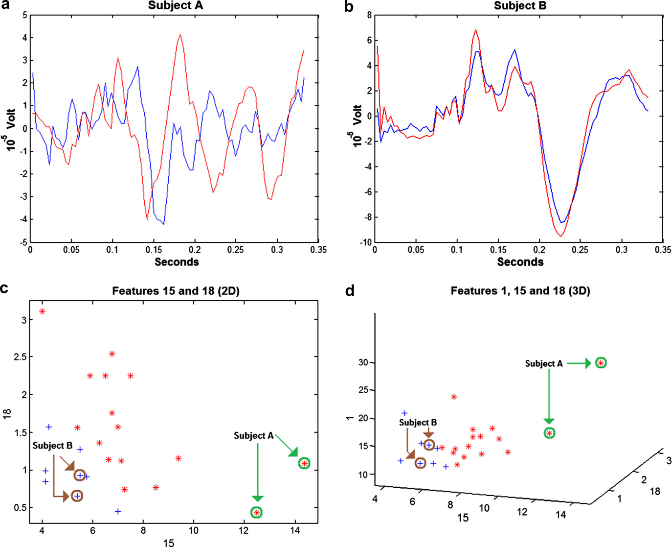
Fig. 3. The EPs of subjects A and B are shown in (a) and (b). The blue and red line indicate the result of two distinct measurements. The twomeasurements of each subject look very similar to the human eye. It can be seen in the 2D and 3D feature spaces of (c) and (d) that the data sets of thesame subject are positioned near each other. Blue crosses represent control subjects, red asterisks represent photosensitive patients. (For interpretation ofthe references to colour in this figure legend, the reader is referred to the web version of this article.)
J. Vermeulen et al. / Clinical Neurophysiology 119 (2008) 842–852
considered, as they hold scale information in addition to
binations feature f.15 is used 59 times (see
weight information.
). Other frequently occurring features are again
Given the information from above it seems reasonable
f.8, f.17 and f.18. They are used 23, 24 and 23 times,
and safe to focus on finding good 3D feature combinations
using the linear classifier on the basic representation.
show graphs of the
feature combinations that performed well according to
3.4. Cross-validation
our analysis (see, e.g.
Cross-validation tests are done according to Section
3.5.3. Sensitivity and specificity
Although 161718 ¼ 816 different unique 3D combinations
ROC curves of f.15, f.18 and the combination of f.15–
can be made with 18 features, only those feature combina-
f.18 are shown in . The features
tions that have significant classification performance are
f.15 and f.18 are combined using the weights of the linear
used (see Section ). With the linear classifier used on
the basic representation there were 206 3D sets with signif-
f :ð15:=18Þ ¼ wðf :15Þ f :15 þ wðf :18Þ f :18
icant classification performance. As mentioned in Section, the leave-one-out and hold-out tests are done using
where w(f.15) 0.29 and w(f.18) 0.71. This information
the linear classifier on the basic representation.
cannot be used to directly draw conclusion about the rela-tive importance of features. To do that scale information
3.4.1. Leave-one-out cross-validation
must be incorporated. It can be seen in, e.g.
shows the average classifica-
that f.15 and f.18 have different scales.
tion error with the leave-one-out cross-validation test.
As expected, the best sensitivity/specificity combination
The three best sets had no errors. The corresponding
is obtained when f.15 and f.18 are combined.
feature sets are [18 15 1], [18 15 7] and [18 15 14]. shows the best 10 sets and their errors.
3.6. Robustness check
3.4.2. Hold-out validation
This check, described in 2.9, gives an impression of
shows the average classifica-
the consistency of the measurements and more impor-
tion errors and their standard deviations of the hold-out
tantly the position of a subject in the feature space. Only
validation test.
the data of the basic representation are taken into
The best set here is [18 16 15], it had an average error
account here.
5%. shows the best 10 sets.
and b show the evoked responses of subjects A
Investigation of the best feature sets has shown that they
and B. The blue and red line indicate the result of two dis-
all rely on features 15 (m) and 18 (second order D). Note
tinct measurements. Especially the two measurements of
that other tests already indicated the usefulness of f.15
subject B look very similar to the human eye, although this
is less obvious for subject A. More relevant though are thepositions of the two measurements of these two subjects in
3.5. Most relevant features
the relevant feature space. It can be seen in the 2D and 3Dfeature spaces of c and d that the data sets of the
As described in Section , we focus here on the occur-
same subject are positioned not far from each other, espe-
rence of different features, in those feature sets that pro-
cially in the case of B.
duce an error smaller than 25% in the cross-validationtests.
3.5.1. Best feature sets of the leave-one-out test
The results of this study indicate that it is possible, using
89 feature combinations produced an error <25%. In
non-provocative visual stimulation, to predict from the
the error fractions of the best fea-
visual evoked potentials whether or not a subject is
ture combinations are shown. In these 89 best combina-
tions feature f.15 is used 63 times (see
Different approaches to represent the evoked response
Other frequently occurring features are f.8,
were tested. The good performance of the basic and PCA
f.17 and f.18. They are used 25, 27 and 25 times,
representations suggests that the alignment destroys dis-
criminatory information. The basic representation givesthe best results.
3.5.2. Best feature sets of the hold-out out test
Combinations of features were found that could be used
Seventy-six feature combinations produced an error
to separate the sensitive and non-sensitive subjects without
<25%. In the error fractions of
provoking a seizure. The most important feature of the
the best feature combinations are shown. The results are
response appears to be f.15 (m, the first order frequency
similar to the results of Section . In these 76 best com-
from the response model).
J. Vermeulen et al. / Clinical Neurophysiology 119 (2008) 842–852
As mentioned before, appropriate linear combination of
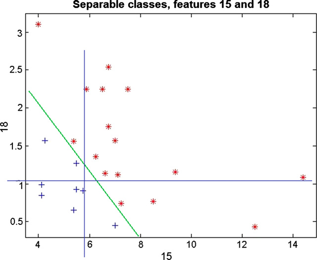
features f.15 and f.18 can separate EPs from sensitive fromthose from non-sensitive subjects and therefore might be agood candidate for practical, non-provocative diagnostics.
This is illustrated in and is also shown in
In conclusion the method described here can be applied
in clinical practice in order to test photosensitivity inpatients without using relatively high frequencies of inter-mittent photic stimulation, and thus avoiding discomfortfor the patient and increasing the safety of the stimulationprotocol.
We thank the Epilepsy Institutes of The Netherlands
Foundation (SEIN) for providing the EEG facilities and
Fig. 4. This illustration shows the usefulness of features 15 and 18. A
clinical data. The assistance and helpful comments of
green diagonal line is drawn to demonstrate that the two classes can be
Demetrios Velis and Wouter Blanes were much appreciated.
separated perfectly. Additionally two blue lines are drawn to demonstratethe thresholds of the voting scheme. The data from the basic represen-
We are thankful for the help and assistance of the col-
tation are used here. The data are not scaled. Blue crosses represent
leagues at the Quantitative Imaging group of the TU Delft.
control subjects, red asterisks represent photosensitive patients. (For
The helpful comments, suggestions and feedback during
interpretation of the references to colour in this figure legend, the reader is
progress meetings and research discussions were of great
referred to the web version of this article.)
benefit to this project.
These results, although based on a relatively small sam-
Appendix A. Supplementary data
ple, show that it is possible to discriminate between photo-
Supplementary data associated with this article can be
sensitive and non-photosensitive subjects. Nevertheless
additional data would be necessary to make meaningful
learning curves.
The main result was obtained using a weighted voting
system what is very basic, since no relation between classi-
fiers is assumed. According to this approach differentparameters are taken individually and a classification is
Gokcay A, Celebisoy N, Gokcay F, Ekmekci O, Ulku A. Visual evoked
obtained based only on that information.
Additionally we tested a linear classifier. The scatter plot
Jirsch JD, Urrestarazu E, LeVan P, Olivier A, Dubeau F, Gotman J.
in clearly shows that a combina-
High-frequency oscillations during human focal seizures. Brain
tion of f.15 and f.18 (can be used to separate the
two classes with a linear classifier.
Harding GFA, Jeavons PM. Photosensitive epilepsy. London: Mac
Keith Press; 1994.
Although additional features may improve the perfor-
Kalitzin S, Parra J, Velis D, Lopes da Silva F. Enhancement of phase
mance, it is clear that the two features f.15 and f.18 are
clustering in the EEG/MEG gamma frequency band anticipates
mainly responsible for good classification. Of these two,
transitions to paroxismal epileptiform activity in epileptic patients
f.15 appears to be more important. The interpretation is
that the discrimination of photosensitive subjects has a
Kalitzin S, Zbijewski W, Parra J, Velis D, Manshanden L, Lopes da Silva F.
strong frequency dependency. Indeed the importance of
Correlation-based alignment of multichannel signals and application to
f.15 in this respect is in accordance with the hypothesis that
paroxysmal events. IEEE Trans Biomed Eng 2002b;49(9):1068–70.
high frequencies are associated with the transition between
Kasteleijn-Nolst Trenite´ DGA. Photosensitivity in epilepsy. Electrophys-
normal and seizure activity
Massey Jr FJ. The Kolmogorov–Smirnov test of goodness of fit. J Am Stat
The interpretation of feature f.18 is less straightforward
Ass 1951;46(253):68–78 (The Matlab implementation was used for the
since it represents the second order distance between the
response model and the measured evoked response. The
Parra J, Kalitzin S, Iriarte J, Blanes W, Velis D, Lopes da Silva F.
value of f.18 tends to be lower for control subjects. From
Gamma-band phase clustering and photosensitivity: is there an
this we can conclude that response model function
underlying mechanism common to photosensitive epilepsy and visualperception? Brain 2003;126:1164–72.
describes more closely the responses of control subjects
Parra J, Kalitzin S, Lopes da Silva F. Photosensitivity and visually
than responses of photosensitive subjects.
induced seizures. Curr Opin Neurol 2005;18(2):155–9.
J. Vermeulen et al. / Clinical Neurophysiology 119 (2008) 842–852
Porciatti V, Bonanni P, Fiorentini A, Guerrini R. Lack of cortical contrast
Rubboli G, Parra J, Seri S, Takahashi T, Thomas P. EEG diagnostic
gain control in human photosensitive epilepsy. Nat Neurosci
procedures and special investigations in the assessment of photosen-
sitivity. Epilepsia 2004;45(s1):35–9.
Le Van Quyen M, Khalilov I, Ben-Ari Y. The dark side of high-frequency
Wilkins A, Bonanni P, Porciatti V, Guerrini R. Physiology of human
oscillations in the developing brain. Trends Neurosci 2006;29(7):419–27.
Source: http://qi.tnw.tudelft.nl/fileadmin/Faculteit/TNW/Over_de_faculteit/Afdelingen/Imaging_Science_and_Technology/Research/Research_Groups/Quantitative_Imaging/Publications/List_Publications/doc/Non_provocative_diagnostics.pdf
Fragen RID: 1) Welches Regelwerk gilt für die grenzüberschreitende Beförderung gefährlicher Güter mit Eisenbahnen? a) RID b) ADR c) VTGGS d) ADNR e) IMDG-Code 2) Welches Regelwerk gilt für die grenzüberschreitende Beförderung gefährlicher Güter mit Eisenbahnen? 3) In welchem Regelwerk finden Sie Aussagen zur allgemeine Sicherheitsvorsorge
Characterization of extended-spectrum beta-lactamase-producing Salmonella enterica serotype Brunei and Heidelberg at the Hussein Dey hospital in Algiers (Algeria). Rachida Kermas, Abdelaziz Touati, Lucien Brasme, Elisabeth Le Magrex-Debar, Sadjia Mehrane, Fran¸cois-Xavier Weill, Christophe De Champs To cite this version: Rachida Kermas, Abdelaziz Touati, Lucien Brasme, Elisabeth Le Magrex-Debar, SadjiaMehrane, et al. Characterization of extended-spectrum beta-lactamase-producing Salmonellaenterica serotype Brunei and Heidelberg at the Hussein Dey hospital in Algiers (Alge-ria).