Pii: s0378-7753(02)00194-5
Journal of Power Sources 110 (2002) 321–329
Battery performance models in ADVISOR
National Renewable Energy Laboratory, Golden, CO 80401, USA
This paper summarizes battery modeling capabilities in ADVISOR—the National Renewable Energy Laboratory's advanced vehicle
simulator written in the Matlab/Simulink environment. ADVISOR's Matlab-oriented battery models consist of the following: (1) an internalresistance model, (2) a resistance–capacitance (RC) model, (3) a PNGV capacitance model, (4) a neural network (nnet) lead acid model, and(5) a fundamental lead acid battery model. For the models, the electric schematics (where applicable), thermal models, accuracy, existingdatasets, and sample validation plots are presented. A brief summary of ADVISOR's capabilities for co-simulation with Saber is presented,which links ADVISOR with Saber's lead acid battery model. The models outlined in this paper were presented at the workshop on‘Development of Advanced Battery Engineering Models' in August 2001.
# 2002 Elsevier Science B.V. All rights reserved.
Keywords: Battery model; Lithium ion; Nickel-metal hydride; Lead acid; Vehicle simulations
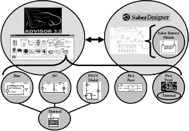
in Matlab/Simulink and Saber, (2) a neural network model,and (3) an electrochemical equation model. Five models are
The National Renewable Energy Laboratory's (NREL)
Matlab-based and the Saber model is accessed via co-
advanced vehicle simulator (ADVISOR ) predicts battery
simulation of ADVISOR and Saber. Saber is a mixed-signal
and vehicle performance for conventional (e.g. non-electri-
and mixed-technology simulation tool by Avant! Corpora-
fied vehicles on the road today), hybrid, electric, and fuel
tion (soon to be Synopsys). These battery models are
cell vehicles as they vary with drive cycle. The purpose of
shown schematically in .
battery models in ADVISOR is to aid in answering systems-
The five Matlab-based battery models available in ADVI-
level questions as follows.
SOR are the following:
Is it better to regenerate electrical energy at a high or low
1. an internal resistance model (Rint),
current to maximize regenerative braking and improve
2. a resistance–capacitance model (RC),
energy efficiency in the overall vehicle system?
3. a partnership for a new generation of vehicles (PNGV)
How can a control strategy optimally heat or cool the
capacitance model (PNGV model),
batteries to get their best performance?
4. a neural network (nnet) lead acid model (PbA nnet), and
If a vehicle's destination and route were known (e.g. via
5. a fundamental lead acid battery model (PbA fund).
GPS), how would the battery be best used?
The Saber model is an equivalent circuit RC model
In order to answer these vehicle systems questions,
characterized for a lead acid battery.
ADVISOR's battery models must be accurate, predict the
This paper gives the equations or equivalent circuit mod-
battery's voltage, current, temperature, and state-of-charge
els for the battery models and presents the accuracy of the
(SOC), and interface with or be written in the Matlab/
models using data taken from battery tests that simulate
Simulink environment. The battery models must be robust
actual driving cycles.
and accurately model the battery chemistries to be used inthe vehicle, including lithium ion (Li-ion), nickel-metalhydride (NiMH), and lead acid (PbA).
2. Internal resistance model
Various battery modeling approaches are available in
ADVISOR, including (1) equivalent circuit models coded
The internal resistance battery model (Rint) was imple-
mented in ADVISOR in 1994. A schematic of the electrical
E-mail address:
[email protected] (V.H. Johnson).
model is shown in The electrical model consists of a
0378-7753/02/$ – see front matter # 2002 Elsevier Science B.V. All rights reserved.
PII: S 0 3 7 8 - 7 7 5 3 ( 0 2 ) 0 0 1 9 4 - 5
V.H. Johnson / Journal of Power Sources 110 (2002) 321–329
Table 1Public datasets characterized for the Rint model
JCI, Horizon, GNB
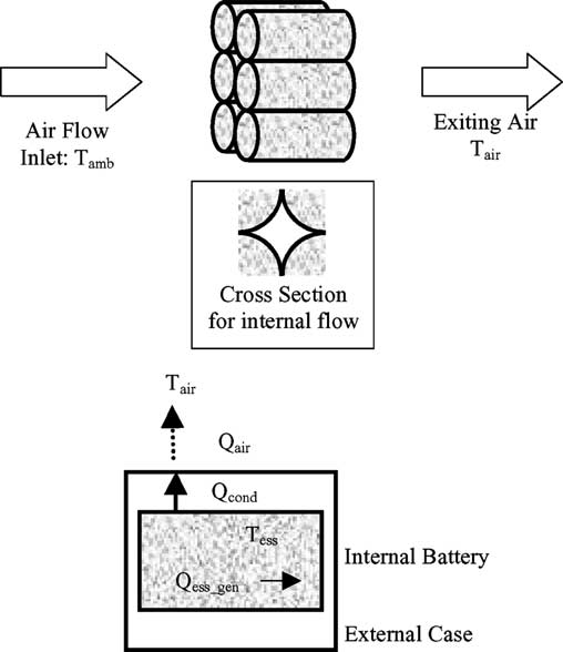
lumped capacity model with air cooling, shown in anddetailed further in .
Fig. 1. Outline of ADVISOR battery models.
The SOC for the Rint model was estimated by performing
amp counting, including Coulombic efficiency losses when
voltage source (open-circuit voltage, or OCV) and a resistor
charging, as shown in
(internal resistance, or R). The parameters vary with SOC,
Idaho National Engineering and Environmental Labora-
temperature (T), and the direction of current flow (e.g. if the
tory (INEEL) originally developed the electrical sche-
battery is charging or discharging). The thermal model is a
matic for the Rint model. NREL development on the modelincluded addition of parameter temperature variation, vol-tage limits, SOC estimator, and the thermal model.
Rint SOC estimator:
Ahmax AhusedðZ
for A > 0 discharge;
for A < 0 charge:
ADVISOR has many Rint parameter sets for various
Fig. 2. Internal resistance electrical schematic.
battery chemistries. Data sources for these parameter setsinclude NREL tests, other national laboratories, manufac-turer data, published sources, and university tests. details the datasets available in ADVISOR.
To characterize parameters for the Rint model for a given
battery, three tests are run: (1) capacity tests, (2) open-circuitvoltage tests, and (3) internal resistance tests. showthe model generation from test results for these threetests. NREL performs these tests over a temperature rangefrom 0 to 40 8C to determine the parameter variation withtemperature.
Fig. 3. Baseline thermal model of a battery in ADVISOR.
Fig. 4. Capacity tests for Rint model.
V.H. Johnson / Journal of Power Sources 110 (2002) 321–329
Fig. 5. Open-circuit voltage tests for Rint model.
Fig. 6. Internal resistance tests for Rint model.
The Saft Rint model was validated in The Rint
as the discharge rate varies from 1 to 100 A. As a result of
model's voltage predictions were accurate to within 3% over
these tests and observed limitations, NREL developed an
fifteen 100 s US06-derived power cycles, with a maximum
improved battery model for ADVISOR that incorporated
error of 12%.
capacitance (the RC model).
Observed limitations of the Rint model are that the
model's voltage response to load changes is too responsive,and the internal resistance does not change as a function of
3. Resistance–capacitance model
the current magnitude. Test results for discharge resistancefor a 1 Ah lead acid battery are given in . The data
The resistance–capacitance battery model (RC) was
shows that the internal resistance can vary by eight times
implemented in ADVISOR in 2001 . A schematic ofthe electrical model is shown in . The electrical modelconsists of two capacitors (Cb and Cc) and three resistors (Re,Rc, and Rt). The capacitor Cb is very large and represents the
Fig. 7. Internal resistance variation with rate.
Fig. 8. Resistance–capacitance electrical schematic.
V.H. Johnson / Journal of Power Sources 110 (2002) 321–329
limits, an SOC estimator, and battery temperature as a
Public datasets characterized for the RC model
function of time.
Battery models for the RC model that are currently
available to the public in ADVISOR are given in
The RC model's parameters are easily determined by
collecting data from the battery using the hybrid powerpulse characterization (HPPC) tests outlined in the PNGVBattery Test Manual The HPPC profile consists of an
ample capability of the battery to store charge chemically.
18 s discharge, a 30 s rest, then a three stage charge profile of
The capacitor Cc is small and mostly represents the surface
2, 4, and again 4 s (Version 2 of the Manual), or an 18 s
effects of a cell, e.g. the immediate amount of current a
discharge, a 30 s rest, then a 10 s charge (Version 3,
battery can deliver based on time constants associated with
In practice, open-circuit voltage tests (are sometimes
the diffusion of materials and chemical reactions. The
also run. As with the Rint tests, NREL performs these tests
parameters vary with SOC and temperature (T). The thermal
over a temperature range from 0 to 40 8C to determine each
model is the same lumped capacity model used in the Rint
model's parameter variation as a function of temperature.
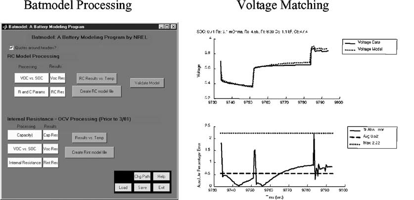
Figs. 10 and 11 show Bat model, an automated data proces-
The SOC for the RC model was estimated by using the
sing and optimization tool that allows the user to develop
voltages of the two capacitors, given in The esti-
models based on actual data, and example RC model para-
mator weighed VC heavily as it represented the bulk energy
meter variation with SOC.
in the battery.
The RC model's voltage predictions are accurate to within
RC SOC estimator:
1% over fifteen 100 s US06-derived power cycles, with amaximum error of 4%. Validated models for Li-ion and
SOCRC ¼ 1 ð20SOC
nickel-metal hydride chemistries can be found in . Sam-
ple plots of the voltage, errors, and SOC comparison/valida-
¼ SOCðV Þ and SOC
tion for the Saft 6 Ah Li-ion battery are shown in Figs. 12
The NREL RC model was based on Saft's two-capacitor
and 13. These validations show that the RC model has
battery model Enhancements were made to the model to
improved accuracy over Rint, and, therefore, better predic-
include temperature and SOC parameter variation, voltage
tions than the Rint model. The SOC comparison in
Fig. 9. HPPC profile for RC model testing.
Fig. 10. Automatic data processing and optimization.
V.H. Johnson / Journal of Power Sources 110 (2002) 321–329
Fig. 11. RC parameters vary with SOC and temperature.
Fig. 12. RC vs. Rint and validation: voltage and errors for one cycle.
shows that there is little difference in the various SOC
predictors () for the initial cycles (e.g.
<200 s). After several cycles, the improved accuracy of
The PNGV battery model (PNGV model) was implemen-
the RC model allows the SOC to track the experimental
ted in ADVISOR in 2001. A schematic of the electrical
estimate for SOC more closely than the Rint prediction. For
model is shown in . The electrical model consists of a
these reasons, the RC model is the preferred model in vehicle
capacitor (C, modeled in parallel with a resistor, Rp), an
internal resistance (R0) an open-circuit voltage (OCV), and asmall second capacitor to represent changing OCV with rate(1/OCV0). The parameters vary with SOC and temperature.
Fig. 13. RC vs. Rint and validation: SOC for 15 cycles.
Fig. 14. PNGV model electrical schematic.
V.H. Johnson / Journal of Power Sources 110 (2002) 321–329
Datasets characterized for the PNGV model
Public dataset characterized for the nnet model
The thermal model is the same lumped capacity model used
SOC in the nnet model was estimated by performing amp
in the Rint model, shown in
counting, including Coulombic efficiency losses when char-
SOC in the PNGV model was estimated by performing
ging, equivalent to the Rint SOC predictor given in .
amp counting, including Coulombic efficiency losses when
Professor R. Mahajan in the mechanical engineering
charging, equivalent to the Rint SOC predictor given in
department at the University of Colorado developed the
nnet model under subcontract with NREL.
The PNGV team developed the PNGV model (PNGV
The advantage of nnet models of batteries is that virtually
Battery Test Manual The model was also implemented
any test data can be used to characterize the model. The most
in the PNGV Systems Analysis Toolkit (PSAT 4.1
applicable tests would be those that used the battery over its
NREL development on the model included addition of
intended operating range. ADVISOR has a single lead acid
temperature and SOC parameter variation, voltage limits,
battery characterized for the nnet model, shown in .
SOC estimator, and the thermal model.
The nnet model was validated over multiple US06 drive
As with the RC model, ADVISOR is currently building its
cycles. The voltage predictions are accurate to within 5%.
set of parameters for multiple battery chemistries for the
One limitation of the nnet model is that the model is only
PNGV model. details the datasets characterized in
valid over the training data's range. The Hawker test data
ranged from a SOC of 27–74% and a power request of
To characterize parameters for the PNGV model for a given
1200 W discharge to 750 W charge. Additionally, the nnet
battery, the same tests used for the RC model need to be run:
model needed overriding at the zero power request case. The
the PNGV Battery Test Manual's HPPC tests (
nnet model is characterized for a lead acid battery, but the
An observed limitation of the PNGV model is that the
technique could be applied to other chemistries. Future
change in OCV with time term (e.g. the 1/OCV0 term) was
enhancements of nnet battery modeling would train the
missing in Version 2 of the model. This was solved by
nnets over a broad range of temperatures, and therefore
including the 1/OCV0 term in Version 3.
have temperature as an additional input. A second thermal
The updated PNGV model is currently being character-
neural network could be trained to represent the thermal
ized and validated and will be available in future releases of
aspects of the battery heating and cooling, or the lumped
capacity thermal model ) could be used.
5. Neural network model
6. Fundamental lead acid model
The neural net (nnet) battery model was implemented in
The fundamental lead acid (fund) battery model was
ADVISOR in 1999 A block diagram of the model is
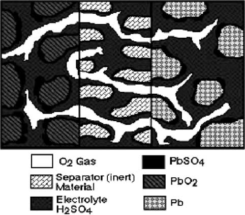
implemented in ADVISOR in 1999 A diagram of
shown in The model is a two layer neural network
the model is shown in . The model is based on
that takes requested power and SOC as inputs and givesavailable current and voltage as outputs. The model wascharacterized for a 12 V lead acid module. Battery test dataat an operating temperature of 25 8C was used to train theneural network model. Due to the limited temperature rangeof test data available at the time of the training of the model,the model did not show a sensitivity to temperature. There-fore, no thermal model is used in the nnet model.
Fig. 15. Neural network block diagram.
Fig. 16. Fundamental lead acid diagram.
V.H. Johnson / Journal of Power Sources 110 (2002) 321–329
physical and chemical reactions for a plate (one-dimen-
sional), such as those given in . The model includes
Public dataset characterized for the fund model
performance and material property variation with tempera-
ture. The thermal aspects of the model include Joule heating
in the electrolyte and energy dissipated in the electrode over-
potentials. SOC in the fund model was estimated by deter-
mining the relative amount of charge available at the limitedelectrode. The model's code was written in Fortran and wascompiled to a dynamic-linked library (dll) to link it with
cycle (voltages were within 3%). The model showed great
temperature agreement with test data.
Fundamental lead acid reactions:
One limitation of the fund model is that good parameter
values are needed for accurate results. The fund model is of
2ðsÞþ3Hþ þHSO4
þ2e @ dischargePBSO
course only valid for lead acid chemistries; however, the
fundamental model shows that ADVISOR can link to more
4ðsÞþHþ þ2e
complex battery codes than equivalent circuit models if the
Professor John Harb in the chemical engineering depart-
user desires.
ment at Brigham Young University developed the funda-mental model under subcontract with NREL.
The input parameters for the fund model are multiple and
7. ADVISOR–Saber co-simulation
fall into four categories:
Co-simulation between ADVISOR and Saber for a con-
1. physical parameters (e.g. cathodic charge transfer
ventional (non-hybrid) vehicle was implemented in ADVI-
coefficient for the Pb electrode, or ratio of gas to liquid
SOR in 2001 . Simulation of the mechanical side of a
volume fractions in the electrode),
conventional vehicle stayed in ADVISOR (Matlab), while
2. numerical parameters (e.g. number of computational
Saber gave extended functionality by simulating the elec-
nodes in the positive electrode),
trical side of a vehicle. ADVISOR–Saber co-simulation was
3. battery characteristics (e.g. initial concentration of
a joint project with Delphi Automotive: first to address
sulfuric acid, or thickness of the separator), and
single- and dual-voltage (see conventional vehicle
4. external limits (e.g. minimum operating battery vol-
systems (2001) and second to address hybrid vehicles
(2002). Through the link with Saber, ADVISOR gainedthe use of an additional lead acid battery model whose
The model was characterized for two 12 V modules,
electrical schematic is shown in The model is a
lead acid plate model, characterizable, and includes self-
The fund model was validated over a variety of condi-
discharge behavior . With respect to a thermal model,
tions. The model showed good agreement with constant
the Saber model's performance varies with input tempera-
current charges and discharges, as well as over a hybrid drive
ture, but there is no transient thermal model to predict the
Fig. 17. Saber dual voltage schematic used in ADVISOR–Saber co-simulation.
V.H. Johnson / Journal of Power Sources 110 (2002) 321–329
Fig. 18. Saber lead acid battery model.
battery's changing temperature. Currently, SOC is estimatedby using the specific gravity at the plate. The Saber modelwas created by Dan Herbison at Avant!.
The link between ADVISOR and Saber was completed
recently (2001), and co-simulation of hybrid configurationsis currently under development (2002). Therefore, much ofthe future work related to co-simulation involves usingSaber's advantages as a mixed-signal and mixed-technologysimulation tool to answer questions as follows.
How do cell by cell performance variations affect pack
Does cell by cell balancing pay off in the overall fuel
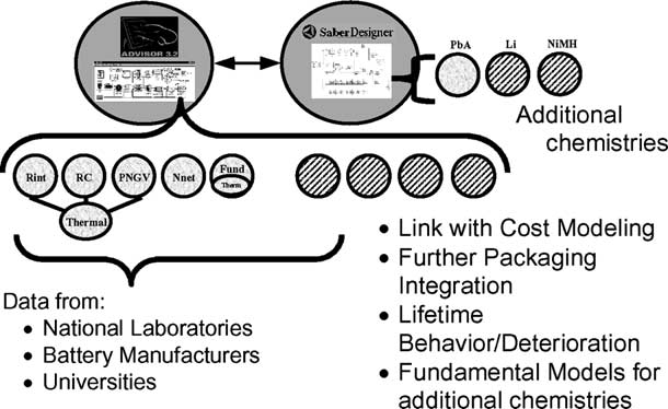
Fig. 19. Summary and future direction of ADVISOR battery modeling
economy of a vehicle?
(diagonal fill represents future opportunities).
What benefit is there to having a multiple energy storage
ADVISOR–Saber co-simulation capabilities can be used
the PNGV model,
to answer these questions using Saber's Monte Carlo ana-
a lead acid neural network model,
lysis feature and the advantages of Saber's underlying
a fundamental lead acid model, and
structure. Monte Carlo analysis with varying parameters
Saber's lead acid electrical RC model.
is easily run in Saber, to aid in cell-by-cell analysis. Cells areeasily connected in the Saber framework as in the physical
The first five models were Matlab-based and the last
world, as the system state equations are assembled by Saber.
model was linked to ADVISOR through Saber co-simula-
Using this feature, the control of each cell can be specified to
tion. For the models, where applicable, the paper showed the
study cell-by-cell balancing, or an ultra-capacitor can be
electrical models, thermal models, SOC predictors, origins,
used with conventional batteries to determine multi-energy
existing datasets, testing, validation, and limitations of the
storage battery pack tradeoffs.
models. The models represented a range of chemistries (e.g.
lead acid, nickel-metal hydride, Li-ion) and a range ofapproaches (e.g. electrical representation, neural networks,
8. Summary and future work
fundamental models). gives a summary of themodels.
This paper summarized the battery modeling capabilities in
Future directions of ADVISOR battery modeling include
ADVISOR, NREL's advanced vehicle simulator. Battery mod-
expanding the library of batteries for the existing models,
els in ADVISOR predict current, voltage, SOC, and tempera-
adding new models (electrical or fundamental), characteriz-
ture of the battery and integrate with the vehicle system by
ing additional chemistries in Saber, and linking with other
using power request as an input. The models presented were:
related models (e.g. cost modeling, packaging, lifetimebehavior). shows a summary of existing battery
an internal resistance model,
modeling capabilities and the future direction of ADVISOR
a resistance–capacitance model,
battery modeling.
V.H. Johnson / Journal of Power Sources 110 (2002) 321–329
Table 6Summary of ADVISOR battery models
þ S.D., 12%maximum
þ S.D., 4%maximum
In future releases
In future releases
OptimaJCI HorizonGNB
through Fortran dll
Ultra-capacitor 2.1
[5] V. Johnson, A. Pesaran, T. Sack, Temperature-dependent battery
models for high-power lithium-ion batteries, in: Proceedings of the17th Electric Vehicle Symposium, Montreal, Canada, October 2000.
This work was supported by DOE's Hybrid Vehicle
[6] V. Johnson, M. Zolot, A. Pesaran, Development and validation of a
Propulsion Program, which is managed by the Office of
temperature-dependent resistance/capacitance battery model for
Advanced Transportation Technologies. The author appreci-
ADVISOR, in: Proceedings of the 18th Electric Vehicle Symposium,
ates the support of Robert Kost, the DOE Program Manager;
Berlin, Germany, October 2001.
Terry Penney, NREL's HEV Technology Manager; and
[7] PNGV Battery Test Manual, Revision 2, August 1999, Revision 3,
February 2001.
Barbara Goodman, the Director of the Center for Transpor-
[8] B. Larson, A. Rousseau, et al., in: Proceedings of the Joint
tation Technologies and Systems. Thanks to Ahmad
ADVISOR/PSAT Vehicle Systems Modeling User Conference on
Pesaran, Tony Markel, Matt Keyser, and Bill Kramer at
Argonne's Hybrid Electric Vehicle Technology Development Pro-
NREL for their input. Thanks to John MacBain and Joe
gram, August 2001.
Conover at Delphi Automotive for their collaboration in the
[9] S. Bhatikar, R. Mahajan, K. Wipke, V. Johnson, Artificial neural
network based energy storage system modeling for hybrid electric
vehicles, in: Proceedings of the FutureCar Congress, 2000.
[10] J.N. Harb, Development and integration of a fundamentally-based
battery model for low-emission vehicle simulations, NREL Report,
[11] J. Conover, V. Johnson, Co-simulation of electrical and propulsion
[1] Advanced Vehicle Simulator (ADVISOR), Version 3.2,
systems, in: Proceedings of the SAE Future Transportation
Technology Conference, August 2001.
[2] Avant! at /.
[12] V. Johnson, A. Brooker, K. Wipke, ADVISOR–Saber co-simulation
[3] Wipke, et al., ADVISOR 3.2 Documentation, see
for single-voltage and dual voltage conventional vehicles, NREL
August 2001.
Report, June 2001.
[4] Simplev Manual, /.
[13] SaberDesigner Documentation, Version 5.1.
Source: http://server3.eca.ir/isi/forum/Battery_performance_models.pdf
Magnetic Resonance in Medicine 62:1609 –1618 (2009) Classification of Brain Tumor Type and Grade Using MRITexture and Shape in a Machine Learning Scheme Evangelia I. Zacharaki,1,2* Sumei Wang,1 Sanjeev Chawla,1 Dong Soo Yoo,1,3Ronald Wolf,1 Elias R. Melhem,1 and Christos Davatzikos1 The objective of this study is to investigate the use of pattern
Relations Homme-Animal Quoi de neuf ? Glasgow en Ecosse est depuis des siècles un lieu de rencontres et d'échanges, centré notamment autour de son université (1450) et du célèbre Collège de Médecine Vétérinaire (1863), devenu faculté en 1949. Glasgow fut aussi l'un des centres importants de l'Art Nouveau, grâce à ses architectes-décorateurs, dont le célèbre Mackintosh. La ville, qui porte toujours les traces de son riche passé industriel (notamment naval), se donne peu à peu un nouveau visage, à grands coups de rénovations urbaines. Ainsi en est-il du « Scottish Exhibition and Conference Centre », bâti sur les anciens docks le long de la rivière Clyde et dont la structure audacieuse ne va pas sans rappeler celle de l'Opéra de Sydney. C'est là que s'est tenue, du 6 au 9 octobre dernier, la 10ème Conférence Internationale sur les Relations Homme-Animal, avec pour thème