Aqb.jp
Part 4 - AQB Implant Prosthesis Chapter 1 - Esthetic restoration and attachment techniques with CAD/CAM
Department of Crown and Bridge, School of Dentistry, Tokyo, Nippon Dental University
Professor Akiyoshi Shinya
I. Esthetic restoration
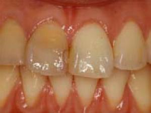
The recent development in dentistry is the need for esthetic restoration that implements the ideology of minimal intervention (MI). The main focus of this practice is to treat by leaving the enamel that has the ability to treat itself as much as possible, and any deficiencies in the enamel or dentin structures is recovered by adhesion treatment with the application of adhesives. This allows the prevention of any leakages by increasing its resistance to acidic conditions, consequently inhibiting the progress of tooth decay or discoloration of the ceramic restoration margins. The application of adhesives to fuse the esthetic restoration apparatus and the dentin not only aids its long-term functions in the oral cavity, but also plays a role in extending the life-time of the tooth. The uses of metal-bonded ceramic crowns or bridges have typically been employed to achieve esthetic restoration thus far. To meet the increased demand in the esthetics, the clinical uses of all-ceramic restorative methods are currently under investigation. The ceramic restorative materials have been utilized in a variety of appliances from the initial inlay, onlay, laminated veneer, crown, to bridges that replaces one to two missing teeth. The zirconia frame produced with CAD/CAM, currently in its developmental stages, has become the centre of attention with the expectations as a ceramic material with high tensile strength that is the same or superior to the metal frame that has been used as the bridge material. In a similar manner, the hybrid resin has been applied widely in the clinical settings, ranging from the crown of the molar regions to the bridges strengthened with fiber. In the following sections, the esthetic restoration materials and the technological developments are discussed. A. Thermo-metal restoration 1. Manufacturing methods for porcelain fused restorative appliances In 1960s, Ceramco, lnc. produced a metal-bonded ceramic crown that plated the ceramics onto the metal and initiating its application to the clinical practices. The unfaltering attempts at research and its application to clinical practices, as well as the development of technology have led to the production of esthetic restoration appliances which are highly appraised. As an example, to a defective central incisor (Fig. 4-1-1), porcelain plated onto multi-purpose alloy (Fig. 4-1-2) for final attachment to the oral cavity as the metal-fused metal crown (Fig 4-1-3) is displayed. Current growthing demand for esthetic finish has progressed to require all-ceramic restoration.
Fig 4-1-1 Loss of esthetics in the right incisor by dental caries
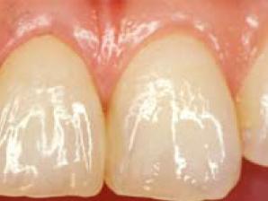
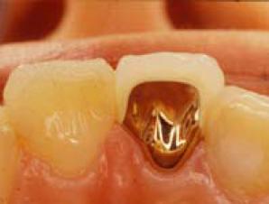
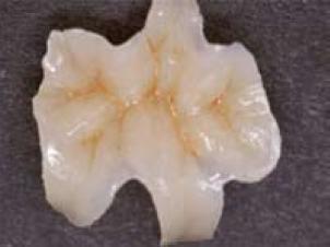
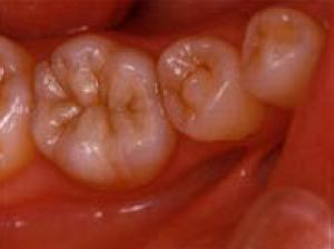
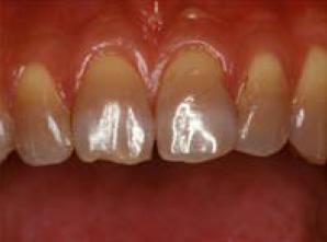
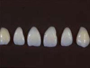
Fig 4-1-2 Metal-bonded ceramic crown constructed with multi-purpose alloys
Fig 4-1-3 Restorative device of porcelain and gold-alloy, in the oral cavity
2. All-ceramic restoration a. Fabrication with refractory investment by direct sintering The working model is fabricated in pouring extra hard gypsum, after the impression of the prepared abutment has been taken with the silicon rubber impression material. Then a refractory model is fabricated by duplicating the trimmed indirect working model, and pouring the phosphate bonded investing material. Apply multiple layers of porcelain directly onto this model, and place this in the furnace. A clinical example is given below (Fig. 4-1-4 to -12).
Fig. 4-1-4 Masticatory dysfunction
Fig. 4-1-5 Fabrication of
Fig. 4-1-6 Inlay attachment to
due to secondary caries of
porcelain inlay with refractory
the enamel and dentin to
mandibular right first molar
restore esthetics
Fig. 4-1-7 Tooth discoloration
Fig. 4-1-8 Laminated shell by
Fig. 4-1-9 Laminated veneer
by the administration of
the application and baking of
that is glued to the enamel
F ig. 4-1-10 Crown fabricated by
Fig. 4-1-11 Porcelain crown
Fig. 4-1-12 Porcelain crown
the application of porcelain to
after its baking step
attached to the dentin,
the refractory investment
improving the aesthetics
b. Glass casting method Cast the molten state of the glass by the lost wax process that follows on from the method of dental precision casting. The casted ceramic restoration undergoes crystallization heat treatment in order to improve its mechanical properties and restore its natural color at the same time. The glass cast crown is casted after the fabrication of the crown with wax to the abutment on the working model, invested in its molten state. A transparent glass crown removed off the investment is shown in Fig. 4-1-13. The glass cast crown that has been colored to mimic that of the natural tooth by crystallization heat treatment is featured in Fig. 4-1-14. Its clinical application is presented in Fig. 4-1-15.
Fig. 4-1-13 Glass cast crown
Fig.4-1-14 Crown reinstated
Fig. 4-1-15 Attached glass
that has been removed from
with mechanical property and
color tone by crystallization
c. Compression molding technique The recovery of its form is conducted with the lost wax method as with the glass casting technique, but with this technique, the block of which its color tone already has been chosen is inserted into the ring. This is then placed into the furnace for it to melt and the construct the shape by applying pressure to the heated, softened form. The compression molded crown is kneaded into its shape in its softened form after the crown has been constructed with wax onto the abutment teeth on the working model as shown in Fig. 4-1-17. The porcelain crown fabricated is shown in Fig 4-1-17, which has been taken out from the investing materials that has been restored with the natural color tone of teeth. Its clinical application is featured in Fig. 4-1-18.
Fig. 4-1-16 Wax pattern
Fig. 4-1-17 Ceramic crown
Fig. 4-1-18 The fitted
waxed up on the working
molded with compression
pressure molding ceramic
and restored with natural
d. CAD/CAM method
The fabrication of ceramic restoration is facilitated with computer-aided design and computer-aided manufacturing. In order to apply the CAD/CAM technology, the scanner has been set up in the dental clinics to enable sending the CAD information to the CAM center on the internet. By applying this novel system into clinical practice, the ceramic restoration appliances have improved the quality of the products, simplified the production process, as well as of the laboratory environment. The CAD/CAM crown is constructed by the measurement of the abutment tooth, and designing the shape of the crown with CAD then this information is used to mechanically reproduce this shape with CAM. The process of crown construction with the application of oil with CAM is featured in Fig. 4-1-19. The fabrication of the CAD/CAM crown is as shown in Fig. 4-1-20, and its clinical application is given in Fig. 4-1-21. The CAD/CAM bridge with zirconia is fabricated by first constructing a zirconia frame (Fig. 4-1-22) aided by CAD/CAM system to which the porcelain is applied, and burned in the furnace (Fig. 4-1-23). The application of this to the clinical setting is featured in Fig. 4-1-24.
Fig. 4-1-19 Ceramic block
Fig. 4-1-20 Ceramic crown
Fig. 4-1-21 CAD/CAM
produced by CAD/CAM system
ceramic crown attached
Fig. 4-1-22 Zirconia bridge
Fig. 4-1-23 Interior of zirconia
Fig. 4-1-24 Fitted zirconia
fitted onto the working model
3. Composite resin restoration a. Hybrid resin crown
The mechanical property of the composite resin has been reinforced to the extent that it is applied to molar crowns. The dimensions of the abutment tooth has been set to be 1.0 to 1.5 mm at the occlusal plane, a clearance of 1.0 mm at the tooth cervix, with margins with the deep chamfer (Fig. 4-1-25). The construction process is conducted by placing the various materials onto the indirect working model in the order of opaque, cervical, dentin and enamel, then project photopolymerization and heat curing before the final polishing step (Fig. 4-1-27). The crown in the oral cavity is featured in Fig. 4-1-30. b. Fiber reinforced hybrid resin bridge Place the fiber 0.1 mm from the bottom of the junction and the pontic (Fig. 4-1-28). The amount of the fiber is 1/2 - 1/3 of the dentin material that was removed. The hybrid resin should be applied in the same away as the crown onto the fiber, undergo photopolymerization and heat curing to finish off (Fig. 4-1-29). Its placement in the clinical setting is shown in Fig. 4-1-30.
Fig.4-1-25 Abutment preparation Fig. 4-1-26 Hybrid resin
Fig. 4-1-27 Fitted hybrid
of the right mandibular secondary crown applied with gloss
Fig. 4-1-28 Fitted onto the
Fig. 4-1-29 Glossed hybrid
Fig. 4-1-30 Fitted hybrid
working model with glass fiber
resin bridge reinforced with
resin bridge reinforced with
4. Clinical evaluation strengthen In prosthetic appliance with excellent esthetic properties, materials such as enamel, dentine, composite resin, metal, and ceramics are an adherend. The success of achieving firm adherence with the polymerization and protection of the dentins lies in the selection of surface processing material and the adhesives with regards to the attachment surfaces. The abutment tooth is created by the resin impregnated dentin by the bonding treatment that has been aimed to protect the dentin and dental pulp complex. Sufficient adhesive strength could not be achieved with the ceramics with the application of adhesive agent alone. The use of an organic functional monomer, -methacryloxypropyltrimethoxysilane (-MPTS) has been valued as a measure to strengthen the adhesive strength of the ceramics in the clinical practice. In the silane reaction, the stable siloxane bonding is formed on the silica or the glass to achieve strong adhesion. By the application of Rocatec method and the adhesion to provide adhesive strength, as well as
prevention of marginal leakage, it should be possible to create a composite dentin that is able to endure harsh intraoral environment. This can also be applied to the high strength alumina or zicornia crown bridge. The application of adhesive agent is also effective in preventing the development of secondary dental caries and discoloration of the crown margin. A case illustrating the importance of the adhesives is presented here. The optic porcelain crown was attached as shown in Fig. 4-1-31, but issues arose with the cervical region becoming sensitive to cold water, and appearance of black line. Upon removal of the crown, the tooth cervix showed that it had turned black in color (Fig. 4-1-32). The marginal leakage resulting from the insufficient adhesion was the cause of this complication (Fig. 4-1-33). This kind of issue should be able to be prevented by a careful operation to apply adhesives.
Fig. 4-1-31 Attached
Fig 4-1-32 Porcelain crown with
Fig. 4-1-33 Coloration of the
the tooth cervix becoming
abutment tooth presenting
sensitive to cold water, and
after the removal
with discoloration
5. Structure of ceramic restoration The structure of the ceramic restoration is shown in Fig. 4-1-34. There are four types of esthetic restorative devices that are currently being employed. The ceramic restorative system that is commercially available is featured in Table 4-1-1. Ceramic metal crown (Fig. 4-1-1 to 3) is fabricated by layering the bonding agent, opaque, cervical, dentin, incisal and enamel porcelain built up on the metal frame. It is completed by adjusting its shape, and grazing to give a glossy finish. The structure of the all-ceramic crown and bridges are created by the application of each layering-porcelain onto the ceramic frame, then to be placed in the furnace (Fig. 4-1-1 to 30). The compositions that have been employed for the ceramic frames include leucite which is used for a refractory model, mica for glass casting, lithium disilicate for pressure injection, and alumina zirconia for CAD/CAM. This is a system to recover esthetics burning porcelain applied onto the high intensity ceramic frame. Dental prosthetic restorative devices such as inlays, crowns and bridges are artificial internal organs and biomaterials that have excellent affinity, functional and esthetic properties. These can even be applied to patients with metal allergies, and it has become a growing interest in the recent years. Implant treatment has been placed as a first-line therapy for the restoration to the area that lacks teeth. The clinical application of the ceramic crown onto osseointegrated implant that can achieve esthetic outcome without the need to mill natural healthy teeth as required for the bridge placement has been much appreciated. Implant has been referred to as the third tooth, and is a system that contributes to preservation of teeth. With the notion of maintaining healthy teeth, it has consequently contributed to the improvement of the quality of life (QOL) of the nation and giving a helping hand in meeting the goal of the 8020 movement.
Transparent
Transparent
coloring
Coloring
Coloring
cervical
cervical
Pressure
Glass casting
Fig 4-1-34 The structures of ceramic restorations
Manufacturing Methods Name of product
Elemental composition
1. Direct firing of
Lamina porcelain
refractory model
G-cera cosmotech II
In-Ceram Alumina
Porous alumina, Glass infiltration
In-Ceram Ziruconia
Porous aluminal, zirconia and glass infiltration
In-Cream Spinell
Porous spinel, Glass infiltration
2. Glass casting
Mica・βspodumene
Kyutai-dentceram
β-calcium metaphosphate
3. Pressure molding
Finesse All Ceramic
Tokuyama Dental
Procera AllCeram
Procera AllZircon
In-Cream YZ CUBES Vident
Table 4-1-1 The manufacturing methods, the product name, manufacturers and the basic compositions of the ceramic restorations
II. CAD/CAM crown The recent acceleration in the development of IT has not only promoted industrial development but also contributed greatly to the technological innovation in the field of dentistry. The current main focus is on the lost wax method that has represented the dental craftsmanship so far in the field of restorative crown, and similarly on the CAD/CAM system that is believed to be the next generation of dental technology. The implementation of dental CAD/CAM system have led to improvements in the quality of the restorative devices; allowed the processing precision to be standardized; simplified the processing steps; and led to improvements in the working environment. The dental technology of the 20th Century had mainly involved the combination of the dental crown material with the precision casting, such as with metal materials, for the construction of the restorative apparatuses. The 21st century dental technology has become focused on the esthetic restoration using the ceramics with the application of the precise mechanical processing with the CAD/CAM system. The dental CAD/CAM system in the past had often limited the material that could be used, but with the recent models that have become commercially available, have overcome this issue, with its ability to adjust the processing conditions and therefore enabling machining of hard resin, titanium and porcelain. For this reason, the materials can now be selected based not only on their functionality, but also their esthetics. Additionally, by implementing the information gained from the jaw tracking device controlled with the computer, this could lead to further understanding of occlusion specific to each patient therefore allowing for improved accuracy of the prosthetic appliances. Problems still remain that needs to be clarified with the prosthetic appliances constructed with CAD/CAM system, before they can be safely applied in clinical practices. In particular, when fabricating the crown, the processing precision of the overall structure of the crown concerning factors have to be fully acknowledged such as: the internal and external of the occlusal plane, proximal plane, cervix and the abutment surfaces; as well as the processing properties of each work materials. Coupled with the development of IT and network systems CAD/CAM network system that transfer the CAD information to the CAM center on the internet has been developed and the computers equipped with a scanner and image processing software have been increasingly placed in the dental clinics. This system allows the CAD information to be transmitted from the dental clinics, therefore enabling fabrication of the restorative devices with only the CAD data that has been derived from the measurements of the working model. This indicates that the working model does not have to be used at the CAM center and that the restorative appliances can be fabricated with the application of digital data. Such application of the innovative IT technology in the field of dental care is discussed in the following sections. A. The types of CAD/CAM systems on the market A wide variety of CAD/CAM systems are available on the current market, therefore in an attempt to clarify each of their properties, the simplified explanations have been summed up in Table 4-1-2. The typical models that are in current use are Cadim (ADVANCE), CERCON (Degu Dent), DECSY (Nissan digital process), EVEREST (KAVO), GN-1 (GC Co.), Prosera (Nobel Biocare), three of which are manufactured in Japan and three remaining are from overseas. Fig. 4-1-35 illustrates the general flow of CAD/CAM system. For the measurement of abutment tooth, there are contact and non-contact methods, wax pattern and
measurement data /computer image for the design, and exclusive CAM for the processing. The times for the production of the restorative appliances are 2 h 10 mins for Cadim, 8 h in total for CERCON that includes firing time, 75 mins for DECSY, 40 mins for EVERST, 90 mins for GN-1, and three days in total for Prosera for the actual measurement time added with the time required for data transmission. The materials that are used in the CAD/CAM system include hard resin, porcelain, titanium, and zirconia, and although the compositions of these materials are different, they can all be processed in the same equipment. There has been a growing interest in the use of zirconia, but the downsides to using this material is that its processing can take a long time needed to machine its half sintering block, and in the sintering after the milling step. The time required in the furnace can vary in each model, but six to eight hours is the standard. All these factors have to be taken into account when selecting the suitable equipment. Product Name
Dental system Center system
virtual design Abutment tooth
tooth model Crown data
Contact type Non-contact
Non-contact Non-contact Non-contact Non-contact
CAM exclusive CAM exclusive
revolutions (rpm) Auto changer
(min, except where stated) CAD time
(min, except where stated) CAM time (min)
Table 4-1-2 Commercial CAD/CAM systems
Form abutment tooth
Impression taking
Take a picture of intraoral with CCD camera, etc
Produce plaster cast
Design with computer
Design with computer
Scan plaster cast
Design with computer
Possessing/ shaving
Fig.4-1-35 Flow chart of CAD/CAM system
B. Machining accuracy of the CAD/CAM crown The dental CAD/CAM system (Cadim, ADVANCE) is featured in Fig. 4-1-36. The machining accuracy of this system was analyzed with different materials by comparing the dimensions of the shape derived with the three dimensional coordinate measurement system to the molds of the abutment tooth and the crown. The materials that were employed as work materials for comparison were: resin block (Hybrid resin, GC Co., code HR), pure titanium JIS second block (JIS H 4650 Daido Steel, code Ti), and 2 types of porcelain blocks [(Cadim Porcelain, ADVANCE, code CP), (Vita porcelain block・Mark II Vita, code VO)]. The cervical margin was observed with the scanning electron microscope. 1. The molds of the abutment tooth and for the crown The molds employed in the experiments for the abutment tooth and the crown (SUS-304), and their respective dimensions are as indicated in Fig. 4-1-37. The abutment with the dimensions: the base diameter of 0.5 mm, diameter of the occlusal plane of 6.0 mm, height of 6.0 mm and the tapered angle on the axial wall to be 8.0, a cervical margin, and the corners on both axial wall and the occlusal plane were rounded with 0.5 mm radii. As for the crown that corresponds with the above structure, the base diameter of 11.0 mm, diameter of the occlusal plane of 8.0 mm, height of 7.0 mm, and tapered angle of the lateral wall as 8.0 was fabricated. The corners for occlusal plane and the axial wall were given a curvature of 0.5 mm radii. 2. Measurement system The state at the time of measuring the dies of the abutment and the crown are illustrated in Fig. 4-1-38. The abutment die was fixed on the Cadim working surface held with a holder. The holder consisted of a cylindrical and a planar section, with the diameter of 6.0 mm for the plane. The base of the abutment die was first attached to the planar section of the holder before connecting the cylinder to the main
component. The two dimensional (2D) measurement of the X-Y flat plane was done at the height that included the maximum height of the contour. The standard measuring range was determined using these outlines obtained from the captured 2D data to conduct the 3D measurement. The crown die was then attached to the abutment tooth, after conducting the crown die measurements, to scan in the same manner. In this study, a cylinder ruby type with 1.0 mm diameter was used as the stylus of probe tip and was scanned using the following parameters: bidirectional probing; radial scanning; 0.05 mm pitch count; 170 mm / min scanning speed; and contact pressure of 70 g. The measuring times for the abutment die, and the crown die, were 25 min and 30 min, respectively. The production of tool paths were conducted as follows, first the crown data was gained by merging the data of abutment die and the external dimensions of crown die gained from the three dimensional measurement on the computer. The internal structures were expanded by 50.0 m for a cement layer. In order to ease the removal of data, one expressed with sprue lines was created and adopted as the model data for the milling process. The tool path was generated implementing the data gathered and using soft trace cut (Renishaw). Two types of toolpaths, coarse and one that was finished to completion, were produced to suit the work materials and the tools employed. The crown data and each tool paths that were employed in generating the sprue lines are featured in Fig. 4-1-39 a to d. The processing apparatus in Fig. 4-1-40 and the CAD/CAM crown that was processed to completion is shown in Fig. 4-1-41, respectively.
Fig. 4-1-36 The dental CAD/CAM system (Cadim) Fig. 4-1-37 The molds of the abutment tooth and
Fig. 4-1-38-a,b Measuring the crown die
Fig.4-1-39 Constructing the tool path a. Crown model data b. Processing of the terrace c. Parallel processing
d. Radial processing
Fig. 4-1-40 Processing apparatus
Fig. 4-1-41 Completed crown
(Left to right) 2.0 mm, 1.0 mm
(Left) HR, Ti, CP, VP
super hard end-mills; 2.0 mm, 1.0
mm electroplated diamond burs
3. Results a. The machining accuracy of the internal and external structures of the crown The means and standard deviations (SD) of the difference between the dimensions, internal and external surfaces, of each crown against the die model and the crown model are presented in Fig. 4-1-42. With respect to the resin block, HR as an example, the machining accuracy of the inner surfaces were as follows: occlusal plane 42.7 (9.0) m to 35.6 (9.7) m at the position 5.0 mm away from the occlusal plane; and 74-2 (7.7) m was indicated for the height, suggesting the machined product was larger with all the dimensions. On the exterior, -0.6 (102) m at the occlusal plane to 23.4 (182) m at the cervical region, and 109.9 (172) m was indicated for the external height, showing a decline in accuracy from the occlusal plane to the cervical region. The internal dimensions for each of the four working materials were shown to expand linearly. The external planes of the CP were shown to reduce from the occlusal plane to the cervix as with the HR. However, this trend was not seen in VP or Ti, where the slight expansion was demonstrated only on the occlusal plane, and then a decrease from the 1.2 mm mark to the cervix was seen with VP. Meanwhile with Ti, an expansion was seen from the occlusal plane to the 3.0 mm mark, but declining after that to 6.0 mm mark where a slight increase was illustrated again. The machine accuracy in all four of the working materials showed an increase in the heights of both the internal and external surfaces
Outside of the crown
Outside of the crown
standard
standard
Inner crown
Outside of the crown
Outside of the crown
Outer crown
standard
standard
Fig 4-1-4-2 Machining accuracy of the internal and external surfaces of the crown
b. The observation of the surface topography with SEM. The SEM photomicrographs featuring the internal cervical region of HR, Ti, CP and VP are shown in Fig. 4-1-43. The surface of HR is shown to be coarse, covered with the passage marks of the tools, and in some areas a continuous filing of roughly 200 m could be observed. In Ti, the machining marks were clearly visible and in contrary to those of HR, CP or VP, presented with sharp angles. CP and VP showed sharp angles on the cervical region with signs of chippings.
Heavy chamfer portion
Fig. 4-1-43 SEM observation of crown cervix margin in each working materials
C. Machining accuracy of CAD/CAM crown fabricated with repeated machining The repeated usage of one processing tool to fabricate multiple CAD/CAM crowns with high accuracy would indicate reduction in the cost and limit the number of tools in the manufacturing process. In this study, the machining accuracy of CAD/CAM crown was investigated with repetitive machining to clarify the limit of the tools to determine the durability of the tools, an issue often faced in the daily clinical practice. 1. Experimental method To evaluate the machine accuracy, 51 CAD/CAM crowns were fabricated with using one processing tool, and in total fabricated 153 crowns with the use of three processing tools. Amongst these, the interior surfaces of the crown numbers 1, 11, 21, 31, 41 and 51 were measured for comparison. 2. Results The machining accuracy of 1, 11, 21, 31, 41 and 51 have been shown in Fig. 4-1-44. The machine accuracy from crown numbers 1 to 51 were shown to decrease from 78 m at the occlusal plane to 36 m in the surface 5 mm away from the occlusal plane, indicating that the surface towards the cervix was becoming narrower. The results also showed that even after fabricating 51 crowns, the dimensions were shown to still be larger than the die, and the cement space had been preserved. The images of the cervical form of the ceramic crown, shown in Fig. 4-1-45, indicated the processing to have retained the reproducibility from numbers 1 to 11, but in the latter fabricated crowns presented with slight chippings. The surface of the bur showed no changes in its structures throughout the experiment.
Fig. 4-1-44 Inner surface machining accuracy of CAD/CAM crown with repetitive
Fig. 4-1-45 Inner surface machining state of CAD/CAM crown which with repetitive
D. Machining accuracy with the application of the CAD/CAM system connected to the internet Coupled with the development of IT and network systems, CAD/CAM network system have developed that can transfer the CAD information to the CAM center via the internet, and computers equipped with a scanner and image processing software have been placed in the dental clinics. The data sent from the dental clinic is only the CAD information derived from the measurement of the working model, therefore the fabrication of the restorative appliances must be done in the CAM center solely relying on the digital data without the working model. In order to fabricate precise restorative appliances, the accuracy in the measurement with CAD is inevitable. A major factor influencing the accuracy in CAD measurements is the step-over, the distance between the lines when obtaining the data. The closer the distance between each of these lines, the more precise the data obtained. The problem that arises as the result of this is the increase in the size of the data and thus increasing the time required to obtain the measurements and processing of the CAD data. In order to overcome this complication, the parameters for an efficient fabrication of crowns with high accuracy need to be clarified.
A study was conducted to enable fabrication of crowns with high machining accuracy with the application network linked CAD/CAM system by comparing the dimensions of the resulting crown and the original die scanned using 3D coordinate measuring machine. The various parameters that were employed to fabricate the studies were: three settings of step-over, 0.01, 0.11, and 0.21 mm, to fabricate crowns from blocks of titanium, porcelain and composite resin. 1. CAD system Dental Cadim (Cadim 107D, ADVANCE, is abbreviate to Cadim thereafter) was adopted as the CAD system for this study. Cadim consists of personal computer equipped with software (Tracecut24, Renishaw) that controls CAD and CAM contact-type measurement. 2. Measurements using the step-over of the molds Scanning parameters adopted were as follows: step-over of 0.01, 0.11, 021; scanning speed, 1000 mm/min; pitch of the abutment surface, 0.05 mm; and pitch of the crown outer surface, 0.1 mm; contact pressure, 30g; and measurement direction to be bidirectional. Cylinder-type tungsten carbide with diameter of 1.0 mm was used as the stylus at the probe tip. The scanning times for St 0.01, St 0.11 and St 021 were, 2 hours and 55 minutes, 18 minutes and nine minutes, respectively for the abutment die; and 3 hours 3 minutes, 35 minutes and 10 minutes, respectively for the crown die (Fig. 4-1-46).
Fig. 4-1-46 Measuring with step-over
3. Transmission of data The scanned data was then compressed into the LZH form, and was then sent to the CAM center with the Cadim mailing software (Advance Co., Ltd.) The data capacity for St 0.01, St 0.11, and St 0.21 were 11.8 MB, 957 KB and 500 KB, respectively. 4. Results a. The difference in the interior and exterior dimensions with the die
The differences in the internal and external dimensions with respect to St 0.01 and St 0.11 were greater than that with the St 0.21 at the distances of 1.2 mm, 2.0 mm and 3.0 mm away from the occlusal plane, respectively. In the regions 4.0 mm and 5.0 mm away, the dimensions became greater in the order of St 0.11, St 0.01, St. 0.21, and with respect to the height, the difference in St 0.01 was greater than both St 0.11 and 0.21. These differences were found to be significant. The least amount of scattering was observed with St 0.01. The differences were shown to decrease from the occlusal plane to 5.0 mm, reduction from 65
μm to 40 μm was observed in St 0.01; 67 μm to 47 μm with St 0.11; and 52 μm to 32 μm with
respect to St 0.21 (Fig. 4-1-47). The difference in the crown exterior and the die with the step-over values were found to be small with St 0.11 at the occlusal plane relative to St 0.01 or St 0.21; in terms of height, St 0.11 was found to have been reduced more than both St 0.01 and St 0.21. The differences were found to be significant. Furthermore, the decrease in the difference from the occlusal plane to the tooth cervix region were found in all step-over values: 23 μm to 1 μm with St 0.01; 11 μm to 5 μm with St 0.11; and 20 μm to -1 μm with St 0.21.
Fig. 4-1-47 Machining accuracy of CAD/CAM with step-over
E. The properties of commercialized internet-based CAD/CAM system The process of internet-based CAD/CAM system is shown in Fig. 4-1-48. As evident from the diagram, the process is fundamentally the same as those that have been mentioned in this chapter, and the only novelty is that the measured data is transmitted on the internet in its digital form. This indicates the reduction in the costs that was spent on purchasing and maintaining CAM, purchasing and storing the blocks and also on the cutting tools. This should result in an overall cut down in the expenses spent on CAM and eliminate the space used for its operation and storage. The CAD/CAM devices of the past were large and therefore were only limited for use in large laboratory centers. The incorporation of internet data transmission should override this past notion. The only space required for CAD is the size of a standard cardboard box, and to set up the personalized computer. This system enables the dentist him/herself to incorporate the finishing touches on those that require high accuracy, and gingival structures onto the computer which are vital steps in the development of dentistry. The internet based CAD/CAM system can be accessed from any part of the world, enabling clinical practice to incorporate the latest technology.
① Abutment preparation The preparative steps are similar to those for the basic all-ceramics crown but conducted by employing the methods recommended by each company to suit the properties of each CAD/CAM system. The errors in CAD measurements arise where the corners are at acute angles. The size of the abutment has to be
larger than the diameter of the milling bur otherwise it would not be able to be applied.
② Impression taking Gingival displacement is critical for creating a definitive finishing line to avoid undercut being formed on the axial and occlusal plane when obtaining impression for the fabrication of fixed restorations.
③ Constructing an indirect working model A particular type of extra hard gypsum for a contact-type measure; and dark extra hard gypsum, recommended by the manufacturer that does not reflect light, employed for the non-contact type (laser) measure. Fabricate the indirect working model with the usual procedure, partition the model and clarify the margin line.
④ Scanning The questions often asked by the dentists are whether this can be operated by themselves and whether it demands time and effort. There are numerous CAD/CAM systems available in Japan, and at least one of these will likely be suitable for your practice. There are contact and non-contact types to scanning. Stylus (probing through physical touch) is usually required for the contact type, with a tip diameter of 1 mm, made of ruby or tungsten carbide, enabling precise measurements to be conducted (Fig. 4-1-49). For the non-contact type scanning, laser is the typical means. Amongst the techniques employed for this type, there is the multi-light band recording method that utilizes the plaster specific for scanning, and photographs once projecting light and shadow. In the methods where the model is optically digitized to precision, there are those in which the complex forms, and obscured sections such as undercut of the working model can be measured and recorded as it is, and be modified on computer to result in a 3D model. With optical impression taking method that is based on technique of triangulation, its main feature is the ability to conduct structural measurement of the abutment immediately within the oral cavity. Simultaneous measurement of the abutment and the adjacent teeth is possible by adopting a specialized channel tray, as well as preparing the devices that can shorten the processing time.
⑤ Construction The construction process from the collected data have been designed that can simply be conducted with the software equipped by each manufacturer that enables simple operation with just a few clicks on the icons displayed on the screen. It is highly user-friendly and will be able to be operated by those who are less apt with IT. It is equipped with functions that can automatically recognize the marginal lines or choose it as an optional setting. For instance, the pontic structure can be selected for a bridge denture, as well as the area of contact in the connector portion; and freely set the distance to the mucosal surface. The setting of the finishing line is shown in Fig. 4-1-50.
⑥ Data transmission Upon finishing the reconstruction procedure, the data is sent in LZH format via the internet.
⑦ Milling and processing At the laboratory centers, milling process is conducted as CAM in accordance with the CAD data sent. The milling tools for each manufacturer are specific with regards to the diamond bur, carbide bur, each with various diameters. In addition, the methods are diverse, including milling from blocks; aluminum oxide powder compacted under high pressure sintering onto the coping; or a powder-slip application method with the electroforming effect with the whole of the denture as the conducting body where the working model is dipped into the electrolyte solution.
① Form abutment tooth
② Impression taking
③ Make a model
④ Scanning
⑤ Design
⑥ Send data via
⑧ Mail restoration
Arrival of
restoration device
Fig. 4-1-48 Internet-based CAD/CAM system
Fig. 4-1-49-a,b Measuring procedure of the abutment and crown with scan a. Contact-type abutment
b. Contact-type crown scanning
Fig. 4-1-50 Setting the line of the margin
F. The machining accuracy of each internet-based CAD/CAM system The processing accuracies of CAD/CAM systems, listed in Table 4-1-3, were investigated. The actual fabrication of crown was conducted using four different routes. First, Dental Cadim 107D measuring device (ADVACE Co., Ltd.) was used to perform contact-type scan. The data was subsequently sent to the processing center, in which the prosthetic crown was also fabricated. Second, a contact-type scan with Procera (Nobel Biocare) measuring device, from which obtained data was sent to the product center in Sweden, in which the alumina crown restoration device was fabricated in the same facility. Third, laser
scanning with GN-1 device (GC Co.) was conducted after which the data was transmitted to the same processing device, to fabricate an In-Ceram crown restoration device. Lastly, laser scanning with Cercon scanning device (Dentsply International) was performed to fabricate a zirconium crown restoration appliance. For this investigation, stainless steel abutment die was employed that was fabricated with consideration to the all-ceramic crown for the molars. Five crown restoration devices were constructed at each manufacturing sites based on these transmitted data. The restoration devices produced are shown in Fig. 4-1-51. The milling tools for each of these restoration devices: Dental Cadim 107D porcelain crown, Procera alumina crown, GN-1 porcelain crown, GN-1 In-Ceram crown, Cercon zirconia crown (each will abbreviated to CA, PN, GR-Po, GN-In, CE, respectively, thereafter) are shown in Fig. 4-1-52. A flat end-mill reamer with 1 and 2 mm diameter were used for Dental Cadim 107D; flat end-mill reamer with 2 mm diameter for GN-1; and fine milling cutter with a 1 mm diameter and rough milling cutter with 2.8 mm diameter for Cercon were employed. The reconstruction with Procera was conducted with the sintering of aluminum oxide at high pressure instead of the method to that mills from a piece of block, thus no tools were required.
Table 4-1-3 CAD/CAM system and restoration materials
Fig. 4-1-51 The fabricated restoration devices
Fig. 4-1-52-a,b,c The milling tools for CAD/CAM a. Dental Cadim 107 D b. Cercon
The processed crown interior is shown in Fig. 4-1-53. The mechanical marks from the milling procedure were visible in GN-Po, GN-In and CE crowns out of the five that were inspected. The images of the internal surfaces of GN-In and CE crowns have been given in Fig.4-1-53. Horizontal markings were visible in the interior of GN-In, whereas both horizontal and longitudinal markings were observed in CE interior. The processing accuracy of the interior of the fabricated crown was analyzed with 3D coordinate measuring device and the results are shown in Fig. 4-1-55. The accuracy with CA decreased from 73 μm near the occlusal portion to 20μm in the abutment. The accuracy values at each measured surfaces were found to be the greatest in PR that resulted in a straight line graph varying around the 110μm. The values for both GN-Po and GN-In were largest closest to the occlusal surfaces with 45.6 μm and 67.2 μm, respectively, but smallest at the point 5 mm away from the occluding surface. The values for CE were the smallest amongst the other crown types. The degree of fit of the crown and the die are displayed in Fig. 4-1-56. A slight gap could be observed with PR that showed the largest differences as shown on the machine accuracy graph. On the contrary, there were no obvious gaps seen with CA, GN-Po or GN-In, indicating a relative accuracy in the fit. The CE crown with the negative values as indicated in the accuracy graph, showed a slight rise above the other types with large gap with the original die. The processing of titanium, ceramics, and hard resin materials were conducted using the internet based CAD/CAM system (Cadim 107D). The crown was fabricated with cement space in the interior of the crown from 1 mm above the cervix region to the occlusal surface with a 50 μm off-set. From the results of the machine accuracy, as shown in Fig. 4-1-58, at points 1.2 mm, 4.0 mm and 5.0 mm away from the occlusion surface, the significant differences in the machine accuracies were evident between the various materials. The machine accuracy of titanium was roughly 60 μm in all of the measured portions, but the accuracy tended to become less towards the cervix region with ceramics and hard resin materials. In addition, significant differences in the machine accuracy between the materials with regards to the crown exterior were also found at all of the measured points. The precision of the CAD/CAM with which crowns were fabricated were shown to be extremely high and thus was concluded there would be no difficulties for it to be applied in the clinical practice.
Fig. 4-1-53 Interiors of each crown
Fig. 4-1-54 Magnified images of mechanically processed internal surface
Fig. 4-1-55 Machining accuracy of each crown
Fig. 4-1-45 Degree of fit for each crown
Fig. 4-1-57 Blocks of titanium, porcelain and resin used
Fig. 4-1-58 Machining accuracy with titanium, porcelain and resin
G. Restoration of color tone The varieties of CAD/CAM blocks provided amongst the different manufacturers are diverse but generally the basic colors referred to as A1, A2 or A3, or a gradation block that combines these are adopted. It is also possible to mill from a basic color block then add staining later onto the dental cleft or to the tooth cervix, for the restoration of natural crown tone. The transparency varies for different materials. With regards to the all-ceramics crown, due to the absence of the opaque material that is often used to mask the metal coping used in the metal ceramic crown, it has more transparency than the latter crown type. This may be an important factor for consideration for some of the treatments or depending on the region. A range of colors for coping are also available for its fabrication with the CAD/CAM system (Fig. 4-1-59) and there is also a sintering method utilized whereby a specialized solution is applied before placing the coping into the furnace. There is even a manufacturer that offers ten different shades for those structures colored with this method. The porcelain is then applied on top of this, thus producing one with a natural appearance (Fig.4-1-60).
Fig. 4-1-59 Alumina porcelain crown incorporating coping
a. Coping was fabricated with CAD/CAM system b. Occlusal plane applied with porcelain c. Porcelain interior
Fig. 4-1-61 All ceramic crown fabricated with CAD/CAM system
H. Installation costs There are devices needed for vacuum, high frequency dissolution and casting devices used in dental precision casting that are relatively expensive. Generally speaking, CAD/CAM systems therefore are not cheap. As shown in Fig. 4-1-2, the prices vary among the different manufacturers, but roughly ten million yen is required to purchase a set, consisting of measuring device, CAD, PC equipped with the software and CAM. However, as mentioned at the beginning, the cost for the CAM can be omitted in incorporating the internet-based system, therefore limiting the expenditure to few million yen to purchase CAD on its own. The added bonus of this system is that the past waxing and casting processes by hand can be entrusted on the machine with a few simple operational settings. The reduction in cost is possible if the restoration devices such as inlay, crown, conus crown, implant superstructure, and plate dentures can be processed, and there will come a period where one system will be installed per dental clinic. The notion of CAD/CAM system has become well known in the dental community, but it has not yet been thoroughly distributed in all of the dental practice settings. The past CAD/CAM system had its limitations, but with this newly developed internet-based system, there are advantages such as reduction in the costs and space; high precision in scanning and processing; and ease in operation of the computer and the devices for the reconstruction without the need for specialized knowledge that make it such an accessible system. The current market demands are treatments with white teeth instead of metals, and one that is cost-effective as a private treatment. The all-ceramics used in this CAD/CAM system has stable characteristics as a block, is less expensive than the metal-bonded porcelain, and can overcome the issues of esthetics encountered with metals due to the development of metal shadows on the gingivae.
1. The search continues for new materials that meet the estheticism requirements as well as in
strength and resistance, combined with cost effectiveness to be applied in clinical practice, in such ways as with the Kaguya-block® (ADVANCE Co., Ltd.) (Refer to Chapter 6 – „The method to mount the superstructure fabricated with CAD/CAM system to the AQB implant‟ for further details).
I believe that the restoration devices will not be able to fulfill the demand for high precision/ high quality that is also cost effective in devoid of the internet-based CAD/CAM system. I highly recommend the use to many of the dental practitioners and assistants.
Fig. 4-1-61 The all ceramic crown fabricated with CAD/CAM system
III. The science behind adhesion and its clinical applications As mentioned previously, the importance of leaving the enamel portion untouched is emphasized by the notion of minimal intervention with estheticism. It has become possible to treat the milled enamel, having regenerating ability, and dentin surfaces by applying adhesive agents. The pH is consequently increased, inhibiting the leakage of ions and thus preventing tooth decay and discoloration of the ceramic restoration devices. The application of the adhesive agents to fuse the esthetic restoration devices with the tooth has been not only been suggested to affect its long-term functions but also in the lengthening the life-time of teeth. The metal-bonded crown bridge, that has sintered porcelain on the metal, has often been applied as esthetic restoration device. The use of all-ceramics restoration has been considered in the clinical practice to meet the rise in demand for estheticism. The science of adhesion and its clinical applications that provides with estheticism are discussed in the following sections. A. Products of adhesive agents Japan has been at the forefront adhesive resin research, in particular with regards to the surface treatment and the adhesion mechanisms to the enamel and dentin. The adhesive agents in the current commercial markets are shown in Fig. 4-1-62, and the product names listed in Table 4-1-4. The commercial adhesive agents are: resin reinforced glass ionomer, MMA-TBB type resin cement and composite resin cement; and the luting agents including, zinc phosphate cement, polycarboxylate cement, and glass ionomer cement. The properties of these luting agents and adhesive materials in terms of chemical engineering are shown in Table 4-1-5. Generally, the time required for it to set range from six to nine minutes, but a longer time of 12 minutes is required for the MMA-TBB type. The pressure required for the composite-type resins is the greatest with 200 to 380 MPa. The key property is its adhesion ability
to teeth, and is the line that has been used to differentiate between the adhesive and luting agents. The properties of adhesive agents, as listed in Table 4-1-6 are, its high mechanical properties, its insolubility in saliva, the ease in operability, not an irritant to dental pulp, and its impermeability to X-ray. The term adhesion is referred to here as the state whereby the adherend (enamel, dentin, resin, metal, and ceramics) are chemically bonded to the cement through adhesive monomers. Cementing, on the other hand, describes a mechanical bonding of the adherend and cement through anchoring with their uneven surfaces as shown in Fig. 4-1-62.
Fig.4-1-62 a-i the different bonding materials that are commercially available
Table 4-1-4 A selection of commercial bonding agents
Compressive Tensile Decay rate Floride
strength (In distilled removal strength to
Cementing Zinc phosphate
Reinforced resin
Table 4-1-5 A table of bonding materials (Taken from „Restorative Preservation, 4th ed‟.) the materials can
be divided into 6 classes, and are provided in powder and solution, or paste/paste forms
1) Mechanical performance must be high 2) Scientific stability must be high and it must be insoluble to oral fluid 3) Coating thickness must be thin 4) Operability must be well and setting time is moderate Powder and liquid must stick well and easy to mix with Operation has time relatively also, and it should harden rapidly after cementing 5) Wet well with Dentin and restoration and it should keep adhesiveness after harden 6) It should not toxicate dental pulp or soft tissue 7) Shrinkage during hardening must be small 8) Thermal expansion coefficient must to close to dentin s and nonconductor of thermoelectricity 9) It should have X-ray impermeabnility 10) A color tone must to close to dentin
Table 4-1-6 The list of bonding material properties
Fig. 4-1-63 Mechanical bonding through the irregular surface structures
B. The bonding technique Measure out the adhesive material onto the mixing slab as shown in Fig. 4-1-64 for bonding the inlay.
After applying the bonding material onto the dentin, insert the inlay as shown in Fig. 4-1-65. Then, carefully remove the hardened adhesive first from the occlusal plane and then the adjacent plane. Inspect the state of the inlay and the tooth after the adhesive removal (Fig. 4-1-67).
Fig. 4-1-64 a,b Operating with the cement material
Fig. 4-1-65 a,b Insertion of cementing agent, and inlay
Fig. 4-1-66 a,b Removal of the cementing material, from
the occlusal surface, and between the adjacent teeth.
Fig. 6-1-67 Cementing completed
C. Bonding to enamel The effects of the dental surface treatment are listed in Table 4-1-7. The improvements in the level of hygiene, prevention of resin leakage and polarization can be expected. The surface treatment of the enamel with phosphoric acid convert it into the mould for the resin to seep through the uneven surface as shown in Fig. 4-1-68, becoming polymerized and set for the two surfaces to be fused together. The phosphoric acid treatment as conducted in Fig. 4-1-69 modifies the surface to become rough as illustrated in Fig.4-1-70. Adhesion is formed after the bonding treatment.
1) The improvements in hygiene and wetting of the tooth plane
The dentin surface was decalcified by phosphoric acid treatment, which also gave rise to a smear
layer, thus preventing the resin leakage can be expected
2) Polarization of dental surface
Hydrogen bonds form between the polarized group of the resin and the terminal groups (-OK, -NH2,
-COOH) of the dentin components polarized by phosphoric acid.
Table 4-1-7 Effects of treatment to the dentin surface
Enamel surface after the
The state of the enamel surface
phosphoric acid treatment (SEM
after the self-etchgin primer
treatment (SEM image)
Fig. 4-1-68 a, b Adhesion with the enamel surfaces
Solubilization and removal of smear layer
Formation of enamel trabeculae resulting in rough edged surfaces
Formation of rough microscopic projections due to the apatite crystals.
Significant enlargement of the surface area
Infiltration and setting of the bonding resin
Strong support is exhibited with the application of masticatory force
Fig. 4-1-69 Etching the dental surface with phosphoric acid
Fig. 4-1-70 Acid treatment of enamel surface Most of the enamel is solubilized by treating with acid solution resulting in height reduction. However new enamel that is rich organic components are continuously generated on the surface that is dense and low in transparency.
D. Bonding to dentin The bonding materials used for dentin surface is shown in Fig. 4-1-71. The adhesive properties of these bonding materials are listed in Table 4-1-8. The adhesion processes to the dentin surface include, solubilization of the smear layer, exposure of collagen, and impregnation of the dentin with resin (Fig. 4-1-72). The smear layer that coats the dentin surface prevents adhesion from being formed. In order to remove this smear layer, a series of steps are taken as illustrated in Fig. 4-1-74. First an etching agent (citric acid) is applied then rinsed with water, and the surface is dried. The collagen surface becomes exposed with the application of primer, ready to form dentin surface imbedded with resin by application of the bonding material, polymerized with light. The adhesion is finally established between the dentin and the resin that consists of hardened 4-META, by its infiltration into the intertubular dentin that has been decalcified by the citric acid that contains ferric chloride.
Fig. 4-1-71 a-g Commercially available
Bonding material
Solubilization of smear layer and decalcification of the dentin surface
Solubilization of smear plug
Decalcification also occurs to the dental tubules and the interior of the tubules
The remaining collagens become exposed onto the surface
Resin-impregnated dentin provides subtle mechanical support
Mechanical strength of the resin tag, hardened after infiltrating into the dentin tubule.
Table 4-1-8 Adhesion with the dentin
Fig. 4-1-72 The adhesion interface between
the resin and the dentin surface
Fig. 4-1-73 The acid treatment of the dentin surface The acid treatment strips away inorganic content of the dentin surface, but the mass remains unchanged. This results in the exposure of organic substances, mainly the water molecules and collagen, onto the adhesion surface, giving rise to a state referred to as "softened dentin".
Fig.4-1-74 Dentin bonding mechanism E. The difference between total etching and self-etching The formation of resin-impregnated dentin and adhesive strength is largely influenced by the dentin treatment used. The smear layer that results from the phosphoric acid treatment is completely solubilized with etching and removed from the cavities by the subsequent rinsing step with water. Whereas with self-etching primer, although the smear layer is solubilized with the acid treatment, the water rinsing does not result in its full removal from inside the crevices. Furthermore the degree of decalcification is less than that with the total etching method, as well as the formation of honeycomb structure or opening of the dentin tubule F. Mechanism of wet-bonding The wet-bonding adhesion as shown in Fig. 4-1-75, prevents the collagen structure from crushing by
removing the excess moisture with blow drying, or by blotting with cotton wool or absorbing paper. The bonding material consisting of hydroxyethyl methacrylate (HEMA) is hardened by photopolymerization, and then the resin is applied to this. The present adhesion mechanisms adopted in dentin bonding are aimed to avoid the collagen from becoming constricted with drying after the decalcification of dentin surface. By preventing the surface from becoming dry, the dentin bonding material infiltrating into the structure and hardening, can bond with the collagen fibers that have remained moist
Fig. 4-1-75 Wet-bonding adhesion mechanism
The collagen fibers remain suspended in its original structure by removing
the excess moisture with slight air blow, cotton wool or absorbing paper
G. Observation of marginal leakage To observe marginal leakage, first, crevices in the external and internal surfaces of natural teeth were formed. To the external cavity, resin cement (Superbond C&B), and acidic cement such as: Vitremer luting cement (3M) or Elite cement (Kerr) were applied before placing the crown. Composite resin was applied to the internal cavity after its bonding with Megabond self-etching primer. The test subject was placed into water set at 37ºC for 24 hours, then preserved in staining solution for further 24 hours at 37ºC, it was separated, and then monitored. The leakage from the cervical region that was observed is shown in Fig. 4-1-76. The crown and whole of the dentin surface with the Elite cement was stained in red showing a large area of leakage. With Vitremer cement, leakage was shown to result from the crown margin and slight staining of the dentin surface. There were no areas of staining seen with either the Superbond C&B (Fig. 4-1-79) or the Megabond (Fig. 4-1-80).
Fig. 4-1-76 a,b Leakage from the margin of the tooth cervix
Fig. 4-1-77 a,b Stained Elite cement Fig. 4-1-78 a,b Stained Vitremer cement
No leakage
Fig. 4-1-79 a,b Stained Superbond C&B Fig. 4-1-80 Megabond
H. Adhesion with ceramics It had been considered difficult to achieve chemical bonding due to the inactive surface of ceramics. Silane coupling was considered an effective method for surface treatment, and is applied in current practice. A selection of silane coupling agent that are commercially available, classified into one, two or three bottle types, is listed in Table 4-1-9. The silane chemical structure is shown in Fig. 4-1-81. The silane coupling agent of three-bottle type is featured in Fig. 4-1-82. The bonding strength of the newer adhesive bonding materials such as Panavir EX and Superbond C&B has increased if applied with the silane coupling material (Fig. 4-1-83), but significantly decreased if placed in 70ºC water bath. To examine the differences in strength with the addition of silane coupling agent, the porcelain blocks were attached together with Panavir EX or Superbond C&B with or without the adjuvant, then was pulled apart. The state of the porcelain after the strength test without the adjuvant resulted in the separation of the bonding material from the ceramics surface with only affect to the interface (Fig. 4-1-84). On the contrary, the destruction state after the test showed the bonding agent to be attached firmly to the ceramics, and resulting in disruption of the adherent (Fig. 4-1-85). The handling of silane coupling agent for its clinical application is shown in Fig. 4-1-86. Add a drop of catalyst solution, universal solution and the activator solution into a dappen-dish (Fig. 4-1-87 to 89), mix well before applying onto the ceramics (Fig.4-1-90). Only apply the bonding agent once the surface has been dried.
Liquid 1 Lamina bond, Porcelain primer
Imperva, Porcelain primer
Scotch prime, Ceramic primer
Liquid 2 Porcelain liner M
GC, Cosmotec primer
Tokuso, Ceramic primer
Liquid 3 Clear fill, Porcelain bond
Table 4-1-9 Silane coupling agents commercially available
Fig. 4-1-81 The structure of γ-methacryloxypropyltrimethoxysilane (MPTS)
Fig. 4-1-82 Silane coupling agent
With silane
With silane
With silane
Fig. 4-1-83 Comparison of bonding strength with or without the different silane coupling agent
Fig. 4-1-84 a,b The disrupted state of ceramics without the addition of silane coupling agent (after 24 hours at 37ºC) a. Panavir EX
b. Superbond C&B
Fig. 4-1-85 a,b The disrupted state of ceramics with the addition of silane coupling agent (after 24 hours at 37ºC) a. Panavir EX
b. Superbond C&B
Fig. 4-1-86 ceramics before undergoing silane treatment
Fig. 4-1-87 Catalyst solution Fig. 4-1-88 Universal solution Fig. 4-1-89 Activator solution
Mix the above solutions well
Fig. 4-1-90 Application of silane coupling agent
I. Adhesion of metals Another issue is encountered when attempting to form chemical bonding with metals, and was the reason for which metals had not been bonded to resins and adhesive materials in the past. In the current practice a primer is applied as a material used to prepare the surface for the subsequent adhesion step. Five types of primers specifically for metals that are readily available on the market are listed in Table 4-1-10. The properties of the primers vary according to the adhesion monomer types. The distinct properties of these primers (Fig.4-1-11) include those for gold-alloy (noble metals), Ni-Cr
(non-metals), extraoral technical use, and intraoral biological use. Thus, the selection must be made accordingly. As shown in Fig. 4-1-91, the bonding strength is improved with the primer treatment in all of the primer agents with the two materials of hard resins tested.
Super bond C&B cementing
New meta color・infes
Table 4-1-10 Comparisons of commercially available primers
Nonprecious metal
Infes・opaque Primer
Table 4-1-11 Properties and application of commercially available primers
Heat cycle
Heat cycle
Primer Primer primer
mer Primer
Fig. 4-1-91 The difference in bonding strength with different primers on hard resins.
J. Removal of adhesion inhibitors The suitability of the testing agent is evaluated with instruments such as fitting checker (Fig.4-1-92) or
rouge (Fig. 4-1-93) for the attachment of prosthetic restoration devices. During the process, the interior of the restoration device usually becomes soiled with layer of silicon oil which can subsequently inhibit the adhesion from being formed. Such inhibitory materials are referred to as adhesion inhibitors. Other examples of inhibitors include finger tip dirt, plaque, tartar, saliva (Fig. 4-1-94), blood, exudates, water, temporary adhesive materials, temporary sealing material, and oils from turbines. These polluting substances from the processes should be removed retain the surface ready to enable the formation of firm bonding to be achieved. There are mechanical means for removal such as sand blast, tooth cleaning device, cotton wool; chemical removal means, such as treatment with acetone, ethanol, etching agents, surfactants. The interior surface of the tooth after removal of inlay, secondary tooth decay and discoloration can be observed from ineffective bonding. The bonding strength and the falling rate of Superbond (Fig. 4-1-96) and Panavir (Fig. 4-1-97) were observed. The adhesive strength was measured once the adjuvants: saliva (SA), fit checker (FC) or green rouge that was solubilized in chloroform (SP) were applied onto the tooth surface, and dried. In comparison to the strength of the control, #600, the reductions in the bonding strength in the presence of inhibitors are clear.
Fig. 4-1-92 Bridge trial placement Fig. 4-1-93 Application of rouge
Fig. 4-1-94 The addition of saliva
Fig. 4-1-95 The interior of the tooth
after the removal of the inlay
Fig. 4-1-96 Bonding strength and the
Fig. 4-1-97 Bonding strength of PE and
rate of reduction
the rate of reduction
References 1) Okada T, Shinya A, Yokozuka S. Effects of load and loading time on fracture toughness with indentation method. Shigaku 1990; 78(3): 460-486. (in Japanese) 2) Watari K, Shinya A,Yokozuka S. Study of adhesive strength and mechanical character of Al2O3. Adhesive Dentistry. 1990; 8: 53-73. (in Japanese) 3) Kuroda A, Shinya A, Matsuda T, Katagiri S. The Mechanical Properties of the Pressable Ceramics and its Optimal Crystalization. Dent Mater J. 2003; 22: 221-230. (in Japanese) 4) Matsuda T, Shinya A, Tomita S, Shinya A, Mitobe T, Hasebe S, et al: A clinical report and a small study of fitness on Procera AllCeram crown. J J Prosthondont Soc 2004; 48: 543-548. 5) Tomita S, Shinya A, Gomi H, Matsuda T, Ogura H, Miyazaki T, et al: Machining accuracy of CAD/CAM ceramic crowns fabricated with repeated machining using the same diamond bur. Dent Mater J 2005; 24(1): 123-133. 6) Tomita S, Shinya A, Gomi H, Shinya A, Yokoyama D: Machining accuracy of crowns by CAD/CAM system using TCP/IP. Influences of restorative material and scanning condition. Dent Mater J 2007; 26(4): 549-560. 7)Lassila LVJ, Tezvergil A, Lahdenpera M, Alander P, Shin-ya A, et al: Evaluation of some properties of two fiber-reinforced composite materials. Acta Odontol Scand 2005; 63(4): 196-204. 8) Shinya A, Matsuda T, Shinya A, Nakasone Y. Hybrid Resin Fixed Partial Dentures Reinforced with Glass Fiber-Optimum Posterior Fiber Frame Design with Finite Element Analysis- Dent Mater J. 2004; 23: 186-192. (in Japanese) 9) Ootaki M, Shin-ya A, Gomi H, Shin-ya A, Nakasone Y: Optimum design for fixed partial dentures made of hybrid resin with glass fiber reinforcement by finite element analysis. Effect of vertical reinforced thickness on fiber frame. Dent Mater J. 2007; 26: 280-289.
Source: http://www.aqb.jp/english/file/ClinicalpracticePart4-1.pdf
VOLUME 2 ISSUE 9 SEPTEMBER 2014 Regional medical practice of concomitant medication CDSCO - REGULATORY MATTERS 1. CONSIDERATION OF ETHNICITY FOR APPROVAL OF NEW DRUGS Severity distribution of eligible subjects. Similarity of dose and dosage regimen. Based on the recommendation of the expert committee constituted by the MINISTRY OF HEALTH AND FAMILY
vie. 29 abr 2016 "LA GRAN BATALLA QUE SE IMPONE ES LA NECESIDAD DE UNA LUCHA ENÉRGICA Y SIN TREGUA CONTRA LOS MALOS HÁBITOS Y LOS ERRORES (.)" FIDEL CASTRO RUZ UN PRINCIPIO JUSTO, DESDE EL FONDO DE UNA CUEVA, PUEDE MÁS QUE UN EJÉRCITO La Última La voz de los más pequeños Jorge Javier Miranda Márquez

