Baronerosso.it

The battery connector must be added to the power side of the controller (black
HYDRA 120 & HYDRA 240 OPERATION MANUAL
capacitors, receiver connector, and red and black wire side). The red wire is the
positive (+) lead, and must match up to the positive lead from your battery. The
black wire is the negative (-) lead, and must match up to the negative lead from
your battery. The polarity MUST BE CORRECT or the controller will be damaged
from reversed polarity.
The Hydra 240 has two SETS of input and output wires. We recommend using a
separate connector for each connection to ensure maximum current capacity.
Make sure and connect the entire battery pack to both input wire sets of the Hydra
240. Do not connect half of the pack to one input, this will lead to operating
problems from potential voltage / current imbalances.
Strip just enough insulation off of the battery wires to solder on your battery
Thank you for purchasing the most technologically advanced brushless electronic
connector to the controller leads. After the connector is soldered and insulated
speed controller in the world for RC boats! Please take the time to read over these
(shrink tubing or electrical tape) check it ONE MORE TIME to make sure the
instructions to ensure you get the most from your HYDRA brushless speed control,
polarity is correct before you plug in a battery.
and enjoy years of trouble-free operation.
1.0 Features of the HYDRA™ :
2.2 Plugging in motor leads:
Extremely Low Resistance (120 is .00043 ohms; 240 is .00022 ohms )
With a brushless system, there is no polarity on the MOTOR side of the controller.
Up to 120 or 240 Amps continuous current
Simply solder the three leads to your motor (recommended) or solder your choice
Water cooled heat sinks (see section 6.0 below)
of connectors to the motor and controller leads. After the throttle calibration routine
Massive 10 gauge wire on Hydra 120 and double 10 gauge wires on
below – if the motor runs backwards with forward throttle, simply swap any two of
the Hydra 240.
the motor/controller connections and it will reverse the rotation of the motor.
12 cells (3s lipo) MAX with BEC
Six to twenty cells, or 2 to 6 cell Lithium Polymer packs
The Hydra 120 and 240 controllers are designed to control one motor. Do not
BEC (3A) provides power to receiver and
attempt to drive two motors with the Hydra 240. Connect the dual outputs of
servo - eliminates separate receiver battery
the 240 to a single motor's leads.
User Programmable Features:
2.3 Connecting to the receiver:
Reverse Throttle Amount
Connect the receiver lead (the three color wires with a connector on the end) to the
Low voltage cutoff (LiPo safe)
throttle channel on your receiver (usually channel 2). Do not connect a battery to
the receiver, as the HYDRA™ will supply power to the receiver and servo through
the receiver connector. If you are using more than 12 cells, or 3s Lipo packs, the
Safe "power on" arming program helps prevent motor from accidentally
BEC must be disabled on the controller. Disable the BEC by removing the red wire
turning on. Always use extreme care with high power systems.
from the receiver connector. Use a separate battery pack or switching BEC (like
Auto shut down when signal is lost or radio interference becomes severe.
our CC BEC) to power the servos and receiver after disabling the BEC.
2.0 Making Connections on your HYDRA™ speed control
3.0 Calibrating the HYDRA™ to YOUR transmitter:
Tools required:
Rosin core electrical solder
IMPORTANT NOTE: Calibration is required for the very first use of the
Wire stripper (optional)
Battery connector
HYDRA™, after updating software using the Castle Link USB programmer, or
Soldering iron (30-40W)
whenever used with a new/different transmitter.
2.1 Adding a battery connector to your HYDRA™:
The HYDRA™ contains a throttle calibration feature that you'll want to use the first
time you power it up with a new/different transmitter. Performing this exercise will
HYDRA 120 & 240 User Guide
Rev 8-date 10/25/07
This document, HYDRA™ software, and HYDRA PCB layout are all Copyright 2004-2007 by Castle Creations, Inc.
teach the controller how your transmitter works.
go to Neutral to confirm that you are ready for the HYDRA™ to ask the next
Disconnect battery
Hold full throttle on your transmitter
You are not required to continue through all five programming options. For
example, if you wish only to change the Reverse Type (option 1) then after
HYDRA™ flashes LED and rings once
programming that setting you can disconnect power from the HYDRA™ and you're
ready to run. Disconnecting the controller in the middle of programming simply
HYDRA™ flashes LED and rings 4 times indicating full throttle measured
retains the values for the remaining programming options that were previously set
HYDRA™ flashes LED while beeping, indicating it's time to push full brake
HYDRA™ flashes LED and rings 4 times indicating full brake measured
The following is a simplified example demonstrating how to "skip" through a
HYDRA™ flashes LED while beeping indicating its time for neutral
program section, how to set a program option, and how to terminate programming
Relax trigger to neutral (center)
early. In this example we will: 1) skip (e.g. do not change) Reverse Type setting,
2) change Reverse Throttle Amount to 12.5%, and 3) terminate programming after
HYDRA™ flashes LED and rings 4 times indicating neutral measured
this option.
Wait for 1 second
3.2.2 Entering Programming mode
HYDRA™ will flash LED and ring twice indicating that it is armed
3.1 Programming Mode
Disconnect battery
Programming the HYDRA™ is as simple as answering a few questions. The
Hold full throttle on your transmitter
HYDRA™ asks questions by flashing a setting number, followed by the possible
setting values. There are five settings that can be programmed in the HYDRA™:
HYDRA™ flashes LED and rings once
1) Reverse Type,
2) Reverse Throttle Amount,
HYDRA™ flashes LED and rings 4 times indicating that it is ready for
3) Cutoff Voltage,
4) Timing Advance,
Continue to hold full throttle
5) Starting Power.
HYDRA™ flashes LED while beeping
You must answer "yes" or "no" to the setting values as they are presented by the
HYDRA™ flashes LED and rings 4 times
HYDRA™. When you enter programming mode the controller will emit a
HYDRA™ flashes LED while beeping indicating that you are in
sequence of beeps and LED flashes that tell you which programming step you are
in. There are two parts to the beep sequence. The first set of beeps indicates the
Let trigger go neutral (center)
‘Setting' Number (e.g., Cutoff voltage type), and the second set of beeps indicates
a Setting Value (e.g 2 cell LiPo). Answering "no" to a Setting Value will cause the
At this point the HYDRA™ will be flashing/beeping the following sequence:
HYDRA™ to ask for the next Value. Answering "yes" to a Setting Value will store
Beep – Pause – Beep… and then Repeats
that setting in the HYDRA's™ permanent memory. After a setting is stored, the
HYDRA™ will automatically continue to the next setting until all settings have been
This indicates that you are at Question 1 and it is asking to accept/reject Value 1.
stored. NOTE: If you answer "no" to all Setting Values for a particular Setting
3.2.3 Skipping Programming Sections – No change required
Number, the HYDRA™ will keep whatever value had been previously programmed.
Only by answering "yes" to a Setting Value will the HYDRA™ store/change that
Looking at the table on the last page you can see that Question 1 is ‘What reverse/
brake type do you want?' and that Value 1 is ‘No Reverse'. We don't want to
change the current value of this option, so we will say no to each value thereby
When answering a question, you will need to move the trigger to the yes (full
skipping the programming option.
throttle) position or the no (full brake) position and keep it there for about 5
seconds. When the HYDRA™ has accepted your answer it will confirm your reply
Apply full brake for 1 second (NO)
by flashing the LED and emitting a beeping tone. Release the trigger allowing it to
HYDRA™ flashes RED LED and rings 4 times, indicating that it has
HYDRA 120 & 240 User Guide
Rev 8-date 10/25/07
This document, HYDRA™ software, and HYDRA PCB layout are all Copyright 2004-2007 by Castle Creations, Inc.
accepted your answer
Every time I throttle all the way up, the controller "cuts off" after a few
HYDRA™ flashes/beeps: ‘Beep – Pause – Beep - Beep' (Question 1,
seconds, even with fresh charged batteries.
The controller will automatically shut down the motor if the battery voltage falls
Apply full brake for 1 second (NO)
below the programmed voltage cutoff (factory preset at 5.0V) for more than half a
HYDRA™ flashes LED and rings 4 times, indicating that it has accepted
second. This is to protect your boat from a loss of control caused by too low a
voltage at the receiver. If the cutoff is kicking in with fresh charged batteries, it
means that the voltage is dropping very quickly. This is usually an indication of a
At this point you will have answered no to both of the questions in Section 1, so
motor that is drawing too much current for the batteries to handle. Try using a
the HYDRA™ will move on to Section 2 without modifying the currently stored
smaller prop on the motor, or using batteries with a higher rating.
Nothing seems to work, receiver and servos are dead, and the throttle is
3.2.4 Changing a Program Option
HYDRA™ flashes/beeps: ‘Beep – Beep – Pause – Beep' (Question 2,
Check all connections to ensure that they are correct, and that the polarity (+/-)
battery connections are correct. If everything is correctly connected, and the
From the Table on the last page, Question 2 is ‘Reverse Throttle Amount'
receiver and servos still do not work, contact the dealer where you purchased your
and Value 1 is '12.5%'. This is the value we want to accept.
HYDRA™ or Contact Castle Creations directly.
Apply full throttle for 1 second (YES)
HYDRA™ flashes LED and rings 4 times, indicating that it has accepted
5.0 Intended Use
your answer.
At this point the HYDRA™ will move on to Setting Number 3.
The HYDRA™ is intended for exclusive use with
3.2.5 Terminating Programming Early
boats only. Use in any other vehicles or aircraft is
In this example, we do not need to change any of the remaining
not covered by warranty and will not be supported
programming options, therefore we can terminate the programming routine
by disconnecting the battery from the HYDRA™. This leaves the
by Castle Creations, Inc.
remaining programming options at their previously stored values.
3.2.6 A Word About Cutoff Voltages
If you are running NiCad or NiMH cells, the default cutoff voltage of the HYDRA™
(5.0V) is normally what you should use, and anything else in the programming is up
to your personal preference to change, so you are ready to run!
** IMPORTANT NOTE: Lithium Polymer Users **
If you are using Lithium Polymer (Li-Po) batteries, DO NOT operate your boat with
the factory default Cutoff Voltage. You MUST change the Cutoff Voltage BEFORE
running your boat.
4.0 Troubleshooting:
Everything is hooked up correctly, the BEC (receiver and servo) works, but
the throttle does not work.
The controller is not seeing the four seconds of neutral throttle and is not arming.
Try moving your throttle trigger slightly in each direction to arm the controller or
follow the calibrating function Section 3.1 above. You may also check to make sure
that your endpoint adjustments on your radio (if it has them) are set all the way
open (both top and bottom, are furthest from zero).
HYDRA 120 & 240 User Guide
Rev 8-date 10/25/07
This document, HYDRA™ software, and HYDRA PCB layout are all Copyright 2004-2007 by Castle Creations, Inc.
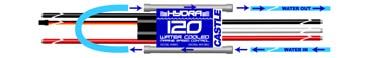

6.0 Water Cooling Tubing
Your HYDRA™ is warranted for one (1) year from date of purchase to be free from
Users must provide their own water cooling tubing.
manufacturing and component defects. This warranty does not cover abuse,
neglect, or damage due to incorrect wiring, over voltage, or overloading.
HYDRA 120
Attach the input and output tubes to one end of the controller. Cut
a section approximately 3.75" long and use it to connect the tubes at the opposite
Each controller is tested for proper operation before it leaves our shop.
end of the Hydra. Make sure the flexible tubes curve gently with no tight bends.
Please see the diagram below for reference.
If you have any questions, comments, or wish to return your HYDRA™ for warranty
or non-warranty repair/ replacement contact Castle Creations at:
Castle Creations Inc.
235 S. Kansas Ave
Olathe, KS 66061
Tel: (913) 390-6939
Fax: (913) 390-6164
HYDRA 240
There are 4 aluminum cooling tubes on the HYDRA 240TM. You
must make three crossover sections of plastic or silicon tubing that are
approximately 3.75-4" long. Connect the input/output tubes to the two aluminum
tubes on the top of the controller closest to the CASTLE text / motor wires.
Connect the bottom controller tubes on the motor side together with a 3.75" inch
length of tubing. Connect the top left tube on the battery side of the controller to
the bottom right tube on the battery side with a 3.75" tube. Now connect the
remaining tubes on that side with a slightly longer tube. The water should flow into
the controller on the top board, flow to the bottom board, then to the other side of
the top board, down to the remaining side of the bottom board and then out of the
Please see the diagram below for reference.
7.0 Contact/warranty information:
HYDRA 120 & 240 User Guide
Rev 8-date 10/25/07
This document, HYDRA™ software, and HYDRA PCB layout are all Copyright 2004-2007 by Castle Creations, Inc.
PROGRAMMABLE FEATURES
NOTE: when stetting Lipo cutoff voltage follow your battery manufacturer's
NOTE: Factory Defaults are indicated by asterisk (*)
No reverse function.
3) Cutoff Voltage
1) minimal cutoff
This setting makes the boat
2) Forward to Reverse
operate freely in forward and
4) Timing Advance
This setting makes your
2) Reverse Throttle
maximum reverse speed
equal to 12.5% of full power
More power/less runtime.
Use at your own risk!
Max power. Most smoke.
This setting makes your
maximum reverse speed
equal to 25% of full power
5) Starting power
Increase the value of this
setting if your model has
This setting makes your
difficulty starting smoothly
maximum reverse speed
under low power.
equal to 50% of full power
This setting makes your
maximum reverse speed
equal to 100% of full
HYDRA 120 & 240 User Guide
Rev 8-date 10/25/07
This document, HYDRA™ software, and HYDRA PCB layout are all Copyright 2004-2007 by Castle Creations, Inc.
Source: http://www.baronerosso.it/forum/attachments/radiocomandi/90508d1231462329-radio-che-non-parla-con-esc-hydra_user_guide.pdf
8722 • The Journal of Neuroscience, September 24, 2003 • 23(25):8722– 8732 Brain-Derived Neurotrophic Factor Modulation of GABAergic Synapses by Postsynaptic Regulation of Rinda A. Wardle1,2 and Mu-ming Poo11Division of Neurobiology, Department of Molecular and Cell Biology, University of California, Berkeley, California 94720-3200, and 2Division of Biology,University of California at San Diego, La Jolla, California 92093-0357
ResearchOnline@GCU Glasgow Caledonian University Short-term therapy with rosiglitatzone, a PPAR-¿ agonist improves metabolic profileand vascular function in non-obese lean wistar rats Naderali, Mohammad M.; Itua, Imose; Abubakari, Abdul-Razak; Naderali, Ebrahim K. Published in: ISRN Pharmacology Publication date: Document Version

